question

glenn-matthiesen avatar image
glenn-matthiesen asked

PV System Grounding and GFPD Application

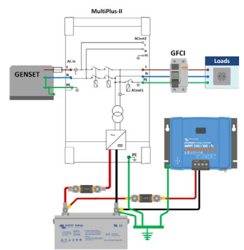
My travel trailer PV system components: Multiplus 3000/24/70, 4 S6-275 AGM Rolls batteries. I am planning the install of a SmartSolar MPPT 100/50 and 2 JKM365M-72-V wired in series.

PV specifications

The SmartSolar 100/50 manual states:

3.2 Grounding

● Battery grounding: the charger can be installed in a positive or negative grounded system. Note: apply a single ground connection (preferably close to the battery) to prevent malfunctioning of the system.

● Chassis grounding: A separate earth path for the chassis ground is permitted because it is isolated from the positive and negative terminal.

As my Multiplus is grounded to the chassis, I would ground the MPPT case to the chassis as well, yes?

● The USA National Electrical Code (NEC) requires the use of an external ground fault protection device (GFPD). These MPPT chargers do not have internal ground fault protection. The system electrical negative should be bonded through a GFPD to earth ground at one (and only one) location.

As this is a mobile application, is a GFPD required?

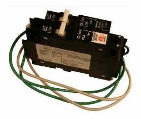
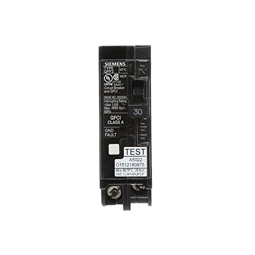
If so, this appears to be the proper device.

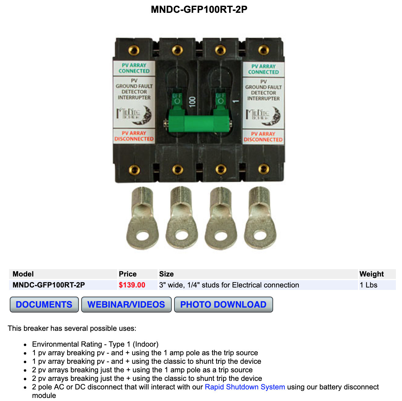
● The charger must not be connected with grounded PV arrays (one ground connection only) You would still bond the PV framing to the chassis, yes?

3.3 PV configuration (also see the MPPT Excel sheet on our website)

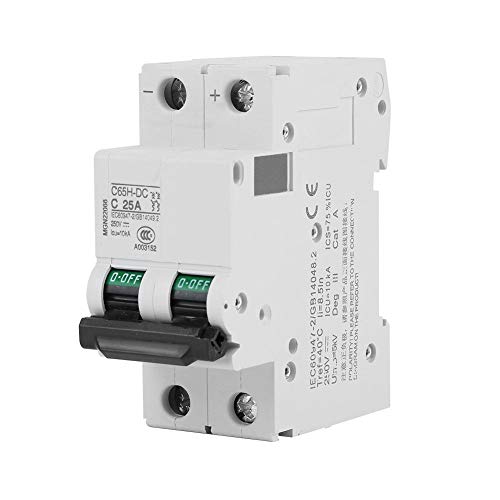
● Provide a means to disconnect all current-carrying conductors of a photovoltaic power source from all other conductors in a building or other structure. I take this as a 150VDC / 20A breaker on the positive leg between the PV array and the MPPT and a disconnect on the negative leg between the PV array and the MPPT?

Apparently to Code, the GFPD must not be used as a disconnect. Should the GFPD be wired before or after the PV array Pos. breaker and Neg. disconnect?

● A switch, circuit breaker, or other device, either ac or dc, shall not be installed in a grounded conductor if operation of that switch, circuit breaker, or other device leaves the grounded conductor in an ungrounded state while the system remains energized. Is this in reference to an "uninterruptible" ground to chassis?

In all my research to date, this is the first time I heard of the requirement of a GFPD. Never heard of it on YouTube PV installs.

Any input would be greatly appreciated.

Grounding
1 comment
2 |3000

Up to 8 attachments (including images) can be used with a maximum of 190.8 MiB each and 286.6 MiB total.

rjoustra avatar image rjoustra commented ·

I am in the same boat about the GFPD in a mobile application since the battery neg buss bar is shown in all Victron drawings to be tied to earth ground or in a mobile application to the chassis.

0 Likes 0 ·
3 Answers
Mark avatar image
Mark answered ·

I prefer not to comment directly regarding the use of a GFPD as its obviously a safety critical item.

A GFPD is connected to your PV wiring (before MPPT) and is designed to detect if there is a current imbalance due to a wiring or system grounding fault on the PV side and if such a fault is detected it will immediately disconnect the PV array as protection.

Electrical codes in different regions specify particular requirements and it would be up to a qualified and experienced local installer/electrician to determine what is required to satisfy your local code. Some codes also have a distinction between 'low' & 'high' voltage for some requirements (generally voltages >100 or 120V are considered as high voltage).

The free online Victron book 'Wiring Unlimited' provides some very good information on the topic of grounding and also includes some basic system schematics - example of grounding for a simple 'off grid system' attached below;

The PV frames should also be grounded to the central grounding point.

In case of a mobile installation the chassis can be used as the earthing point for the grounding bus bar.

You should pay particular attention to ensure that each item only has a single ground path to the common grounding point/bus bar to avoid ground loops.

Note that the DC ground cabling should also have sufficient cross section to be able to carry a fault current at least equal to the DC fuse rating (this is commonly overlooked)

Link to Wiring Unlimited book (section 6 is related to grounding);

https://www.dropbox.com/s/pdkngditufe0zfb/Wiring%20Unlimited.pdf?dl=1


There are also several very detailed complete 'system schematic' examples on the Victron Energy website, in the 'downloads' area;

https://www.victronenergy.com/support-and-downloads/systems#item=system-multiplus

These 2 examples would be good references for you;

https://www.victronenergy.com/upload/documents/MultiPlus-system-example-5KW-24V-230V-AC.pdf

https://www.victronenergy.com/upload/documents/VE-Bus-BMS-example-with-3KW-12V-MultiPlus-230-Volt-revision-B.pdf


1563245883568.png (132.4 KiB)
2 |3000

Up to 8 attachments (including images) can be used with a maximum of 190.8 MiB each and 286.6 MiB total.

glenn-matthiesen avatar image
glenn-matthiesen answered ·

Thanks again Mark for your solid advice. I had a read through of Victron's Wiring Unlimited. An essential resource for anyone planning a renewable energy system.

It is curious though, with regard to the installation of an RCD(s) within a system, no mention is made of the NEC Code requirement that an RCD must be installed between a PV array and the MPPT. While this may not be an international standard, it is certainly a best practice. Also, there appears to be no mention of grounding the PV frames, an obvious best practice.

This information should be included within 4.10 Solar panels and page 56, Where to mount a RCD.

In any event, I have ordered the following components for my installation. I am providing the following Links as searching and sourcing these components took some time.

---

Edit by moderator: removed referral links spammed in multiple topics.

---

Thank you again Mark for steering me in the right and safe direction!

Cheers,

Glenn


30a-gfci.jpg (16.9 KiB)
63a-gfcb.jpg (11.6 KiB)
din-enclosure.jpg (21.0 KiB)
30a-gfci.jpg (16.9 KiB)
2 |3000

Up to 8 attachments (including images) can be used with a maximum of 190.8 MiB each and 286.6 MiB total.

glenn-matthiesen avatar image
glenn-matthiesen answered ·

Correction: The grounding of PV frames is mentioned on page 62 under Off-grid system grounding.

2 |3000

Up to 8 attachments (including images) can be used with a maximum of 190.8 MiB each and 286.6 MiB total.

Related Resources

Additional resources still need to be added for this topic