question

Phil Gavin avatar image
Phil Gavin asked

Multiple shunts on single BMV 702

I used to have a 24V system so the cabling is very heavily sized. (Multiples of 50mm2).

I have changed to 48V now, but I figure the heavier Cu cables are still serving me well.

I have 1200AH of batteries, 48 x12V, arranged in 3 physical banks, each bank from its own set of busbars.

The long and the short of it is that there is no real bottle neck of cabling that is suitable to add a single shunt. Ideally, I need to fit a shunt in a minimum of 3 places.

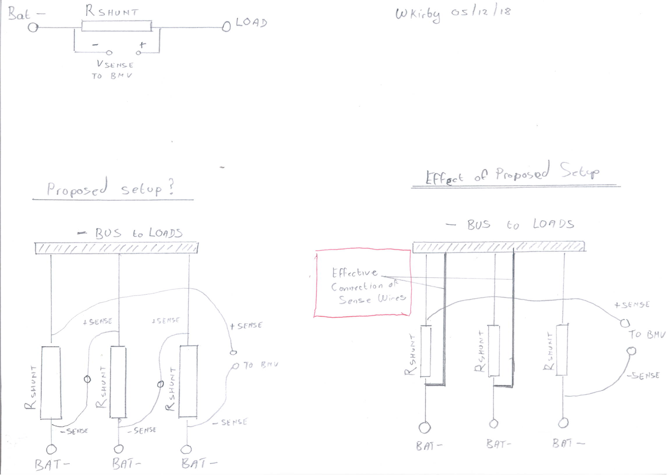
Ideally, I want to install say three 1000A shunts in parallel to the batteries and put the output in series to the BMV. I could then tell the BMV it's a 333A/50mV shunt.( Which the manual suggests can be done).

But I've never physically handled the BMV device, so before I go out and buy one I like to know if this is doable, in other words, that the shunt's output is an analogue mV output and not digitized before it gets to the BMV.

BMV Battery Monitorbmvbmv702
2 comments
2 |3000

Up to 8 attachments (including images) can be used with a maximum of 190.8 MiB each and 286.6 MiB total.

Peter Polz avatar image Peter Polz commented ·

Thats is definitly not the correct way to handel that. With 3 physical banks you have always to monitore each seperatly. You never can determine a Problem if you do it any other Way. So that means one BMV for each bank is a logical consequence.

0 Likes 0 ·
markus avatar image markus ♦♦ Peter Polz commented ·

Hallo PolzSolar :o) Endlich! Welcome!

0 Likes 0 ·
11 Answers
Phil Gavin avatar image
Phil Gavin answered ·

@WKirby

I am glad you drew that out, it appears to me that it wont work as you've drawn it.

(Which is what I had in mind).

That's because the secondary shunt wiring will effectively create a path between the battery and the load that will bypass the shunt.

As I see you also stated.

Back to the drawing board.

1 comment
2 |3000

Up to 8 attachments (including images) can be used with a maximum of 190.8 MiB each and 286.6 MiB total.

wkirby avatar image wkirby ♦♦ commented ·

I wish it provided a solution rather than demonstrate a problem.
I guess it's back to the drawing board. If I think of something a little less crazy than precision differential amplifiers and precision summing amplifiers then I'll surely update this thread.

0 Likes 0 ·
wkirby avatar image
wkirby answered ·

If you did that, you'd need to tell the BMV that you have a 3000A/50mV shunt, not a 333A/50mV shunt. You have applied the maths for resistors in parallel, the current carrying capacity of the three 1000A shunts in parallel goes up to 3000A. In other words, you'll need 3000A amps to flow to get 50mV drop across the parallel trio.
Also, getting equal current sharing amongst the three separate parallel shunts is going to be tricky. You'll only be connecting the BMV to one of the three, so it will almost certainly be inaccurate.
Having said that I'm sure I saw reference to a 6000A/50mV shunt somewhere. However, this introduces lower resolution measurements. Now, 1A is only bing represented by 8.3μV (16.6μV for 1A with a 3000A/50mV shunt). I don't know how many bits the ADC in the BMV is, nor do I know what the ADC reference voltage is, but I wouldn't be surprised if you loose your decimal places when using a 6000A/50mV shunt. The single decimal place you get for Amps when using 500A/50mV shunt is being represented by just 10μV
Those great big shunts are really only designed for massive installations where 2000A is a daily average and nobody cares about decimal places.

I understand where you are coming from regarding minimising losses, but really, with a 500A/50mV shunt with 500A going through it you are only burning 25W.
I'm not sure about the size of your system. Do you get up in the hundreds of Amps at all?

It's really a case of sacrificing (low) losses for resolution.
I hope I made sense there! :)

EDIT: Yes the Analogue to Digital Converter is inside the BMV, not the shunt. I'm pretty sure there are no amplifiers on the shunts either.

2 |3000

Up to 8 attachments (including images) can be used with a maximum of 190.8 MiB each and 286.6 MiB total.

Phil Gavin avatar image
Phil Gavin answered ·

Nice to stir up some healthy dialogue.

@ peterpolz

They are 3 physical banks, but they are a single electrical bank.

Can you monitor 3 separate banks? I don't know.

I'd settle for that even, but I don't think you can. I don't think the ESS accepts that.

Leastways I have never seen a 3 battery bank example on the WWW.

So, I believe one would need a single BMV.

Open to comment on this point though.

@ Wkirby

Thank you for your reply.

I think I was clear in my original post that while the primaries of the shunt are in parallel the secondaries would be in series. I am aware that I want to operate in the accurate resolution "zone".

I've considered it further.

We are in fact both incorrect, as the shunt would neither be 3000A/50mV nor 333A /50MV

It would still remain a 1000A/50mV.

An Amp generates X mV regardless of which shunt it flows through, all these voltages are summated in series.

300A =15mV through a single shunt, but through 3 shunts the current would be thirded, a 100A through each shunt = 5mV +5mV +5mV =15mV. Same thing.

The driver for this is to overcome the physical limitations of my cabling, losses would be identical.

"EDIT: Yes the Analogue to Digital Converter is inside the BMV, not the shunt. I'm pretty sure there are no amplifiers on the shunts either. "

If you are correct I have my answer: it can be done.


2 comments
2 |3000

Up to 8 attachments (including images) can be used with a maximum of 190.8 MiB each and 286.6 MiB total.

wkirby avatar image wkirby ♦♦ commented ·

Oh yes, I had indeed misunderstood. I'm very sorry. Yes, that would be 1000A/50mV in that configuration.

But, I have thought of a new problem. You'll be connecting the negative sense wire of one shunt to the positive of the next one in series, this should short circuit the sense wiring. I think I'll have to draw it once I have access to s pen and goddesses old fashioned paper :)

0 Likes 0 ·
Phil Gavin avatar image Phil Gavin wkirby ♦♦ commented ·

Yes, it would have to connected in a positive to negative manner, does the shunt support a two wire connection?

0 Likes 0 ·
Peter Polz avatar image
Peter Polz answered ·

@Phil_Gavin Yes i do can do that. I simpel read out values of each BMV over modbus from venus, recalcuate them and set on over SOC by modbus as corrected VE.Bus SOC, This was handled by one connected arduino to lan. That's the Geekway :)

If you are not able to do that, people simple take one BMV for each bank an one common for all.

2 |3000

Up to 8 attachments (including images) can be used with a maximum of 190.8 MiB each and 286.6 MiB total.

Phil Gavin avatar image
Phil Gavin answered ·

@Peter Polz

"handled by one connected arduino" - I want to avoid this if there is a more elegant solution.

"people simple take one BMV for each bank an one common for all"

Again it is electrically only one battery bank, that single battery bank is physically arranged in 3 groups. I only care about the overall SOC of the entire electrical bank, but if I could monitor one common BMV for all, I wouldn't be asking this question.

2 |3000

Up to 8 attachments (including images) can be used with a maximum of 190.8 MiB each and 286.6 MiB total.

Peter Polz avatar image
Peter Polz answered ·

Where is the Problem? Split up connection after Busbar .. connect all 3 connections to one Shunt and connect shunt to another Busbar.. Problem solved for you. If you dont want to monitor each bank seperatly why do you want to take 3 shunts? may you show us some Pictures of your installation?

Also again it is an absolutly fatal installation mistake if you don't monitor each parallel connected bank in an big system with parallel conneced banks, thats not the way you should handle such a sytems, becaus your overall SOC will be completly wrong if one bank make problems and as a consequence you are not able to monitor that one bank fails

2 |3000

Up to 8 attachments (including images) can be used with a maximum of 190.8 MiB each and 286.6 MiB total.

wkirby avatar image
wkirby answered ·

Here is a diagram of what I hope is correct in my understanding of what you have in mind.

Top left: The basic illustration of measuring voltage over a shunt, I'm sure you know this.

Bottom left: An illustration of how I understand your thinking. Seems like it should work.

Bottom right: Closer scrutiny reveals that the sense wire connections are effectively bypassing two of the shunts.


Does this make sense (pun, sorry)?
I'd actually be wiling to conduct an experiment to provide a practical demonstration of this.


multiple-shunts.jpg (140.9 KiB)
1 comment
2 |3000

Up to 8 attachments (including images) can be used with a maximum of 190.8 MiB each and 286.6 MiB total.

markus avatar image markus ♦♦ commented ·

I would consider, to put a BMV on each shunt for diagnosing the asymmetric and equip one shunt with 2 BMVs where the second one is set to mV/3 to have an estimated overall SOC and report to Venus for example without Arduino or anything.

Just a thought.

0 Likes 0 ·
Phil Gavin avatar image
Phil Gavin answered ·

Thanks, but as per my original statement:

"The long and the short of it is that there is no real bottle neck of cabling that is suitable to add a single shunt."

remains true.

The number of cables(12 pairs), their sizes, and their separate routes precludes this option.

I don't want to diverted off on a system layout/design tangent. I have the layout I have.

Yes, things can go wrong with parallel strings, but the budget dictates that those bridges get crossed, if and when they arise.

5 comments
2 |3000

Up to 8 attachments (including images) can be used with a maximum of 190.8 MiB each and 286.6 MiB total.

markus avatar image markus ♦♦ commented ·

As I wrote above

"I would consider, to put a BMV on each shunt for diagnosing the asymmetric and equip one shunt with 2 BMVs where the second one is set to mV/3 to have an estimated overall SOC and report to Venus for example without Arduino or anything.

Just a thought."


If you are really not interested in monitoring asymmetric; 1 BMV to one shunt and mV/3?

0 Likes 0 ·
Phil Gavin avatar image Phil Gavin markus ♦♦ commented ·

Yes, 1 BMV to scaled to estimate all is certainly doable and a strong contender as all 3 banks are equally sized.

0 Likes 0 ·
markus avatar image markus ♦♦ Phil Gavin commented ·

I would simply not have the balls to let an energy storage of this size unmonitored in symmetry.

How many cells are involved in your setup? And what will happen if one cell fails and you don't get it fast enough...

0 Likes 0 ·
ben avatar image ben ♦ markus ♦♦ commented ·

At least if this is a lithium battery, no one should be using a BMV to do charge management/safety thresholding in the first place.

So, whatever motivation Phil has for SOC estimation, he should separately have the right cell monitoring and disconnect apparatus in place to protect his investment and for safety reasons.

In the event that a monitoring system drops a string in a parallel design, at that point any BMV-based estimation will be inaccurate, since the BMV will not know that the pack just lost capacity. But, this is a relatively minor issue.

0 Likes 0 ·
Phil Gavin avatar image Phil Gavin markus ♦♦ commented ·

Regarding string symmetry issues when I get around to it I'll install a pzem-051 per string. It is a dc kWh meter, about 12 bucks a piece. I'll orientate the meters to measure accumulated charge per string.

Any significant disparity should flag an issue.

There are also battery balancers coming.

But 1 issue at a time.

0 Likes 0 ·
Phil Gavin avatar image
Phil Gavin answered ·

@WKirby

Yes, something along the lines of your proposed setup is what I had in mind.

Interested to know your findings.

2 |3000

Up to 8 attachments (including images) can be used with a maximum of 190.8 MiB each and 286.6 MiB total.

ben avatar image
ben answered ·

One thing to think about is that the individual banks may contribute current at rapidly oscillating levels. That's what I observe on my parallel strings, when I put clamp ammeters on them individually while the whole pack is under a steady load.

The computer (BMV) samples the shunt at regular intervals and sums the results to estimate net energy. If there is any sample-and-hold going on at the sense PCBs, I think you could get a very inaccurate sum if they have a timing issue.

On the other hand, if they are just passing through the (analog) value, I would guess that would be okay. From memory, those PCBs just have a few discrete analog components on them, but no digital ICs. So probably what you're proposing would work.

I'm having a hard time imagining a layout where you don't have everything bussed up somewhere. Is that not the case? At that point, is there just no physical room to install a single shunt? I know you are tired of people asking you to do something you've already ruled out, but your response in that area seems to be focused on all the 24 wires running everywhere, when really it is the wiring after the bus-up point that is in question.

2 |3000

Up to 8 attachments (including images) can be used with a maximum of 190.8 MiB each and 286.6 MiB total.

Phil Gavin avatar image
Phil Gavin answered ·

@ben

There are 12 x 16mm2 cable to the positive and negatives of the batteries respectively.

The MPPT's and the inverter cabling is also on these busbars.

If am to go to trouble adapting the cabling I would need to mount two more mini busbars with a shunt between them, because the smaller shunt wont accommodate that many connections.

Then if I am prepared do that then I may as well mount the 6000A/50mV shunt which will accommodate that number of connections and cut the fins to bring it down to an acceptable resolution.

I could re-calibrate with a DC clip-on ammeter and set the BMV accordingly.


1 comment
2 |3000

Up to 8 attachments (including images) can be used with a maximum of 190.8 MiB each and 286.6 MiB total.

ben avatar image ben ♦ commented ·

I see, all the loads and chargers are also sharing those busses. It makes sense it would be a lot of hassle to rewire.

0 Likes 0 ·

Related Resources

Additional resources still need to be added for this topic