question

Yusef Neblett avatar image
Yusef Neblett asked

L1/L2 Multi+ measurement readings on a 230v Split Phase with Autotransformer

Hi,

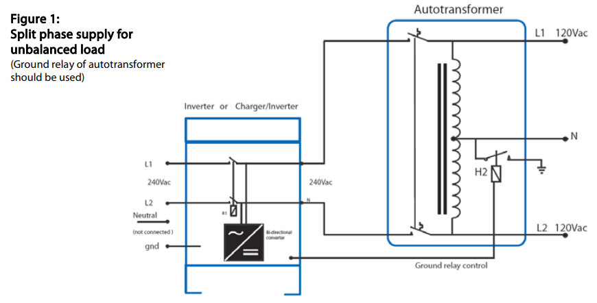
I have setup a 48/5K/70 Multiplus for a Home Split-Phase configuration, using the Autotransformer Diagram below where L1 is connected to the L1 on the Multi and L2 is connected to the N on the Multi and then using an Autotransformer to step down from 230v to 115v/115v


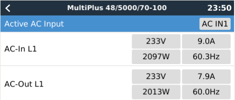
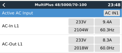
My question is: Is this taking the measurement that shows in CCGX and VRM from L1+L2 phases? is the value showing there is a total from L1 and L2, or it is only showing L1 (phase1)?


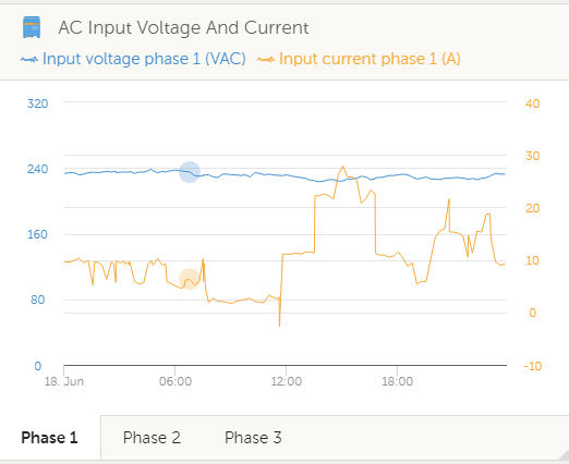
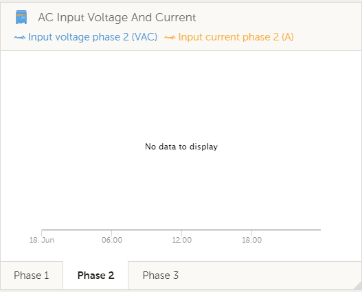
VRM shows data only for Phase 1 and not for phase 2

Autotransformersplit phase
1560919388579.png (71.8 KiB)
1560919792728.png (26.7 KiB)
1560919898874.png (26.7 KiB)
1560919951979.png (23.9 KiB)
1560920142005.png (30.8 KiB)
1560920169739.png (17.9 KiB)
2 |3000

Up to 8 attachments (including images) can be used with a maximum of 190.8 MiB each and 286.6 MiB total.

2 Answers
wkirby avatar image
wkirby answered ·

Those measurements are being taken for current flowing out of the MultiPlus its self. It is the sum of L1 + L2. There are no current measurement sensors in the Autotransformer to allow separate L1 or L2 current.

2 |3000

Up to 8 attachments (including images) can be used with a maximum of 190.8 MiB each and 286.6 MiB total.

Yusef Neblett avatar image
Yusef Neblett answered ·

Hi WKirby,

Thanks for your answer. It is understandable that the readings are made by the multiplus and not on the transformer.

Since I am feeding the ACin from the grid with 2phases I was expecting to see phase 1 and phase 2 in separate reading. But looks like there is no way to configure 1 Multi to read and show the reading by phases.

2 |3000

Up to 8 attachments (including images) can be used with a maximum of 190.8 MiB each and 286.6 MiB total.