question

frithjof-plahte avatar image
frithjof-plahte asked

100 volt AC ripple on DC side. Victron Multi Compact 12V/2000VA/80 Amp.

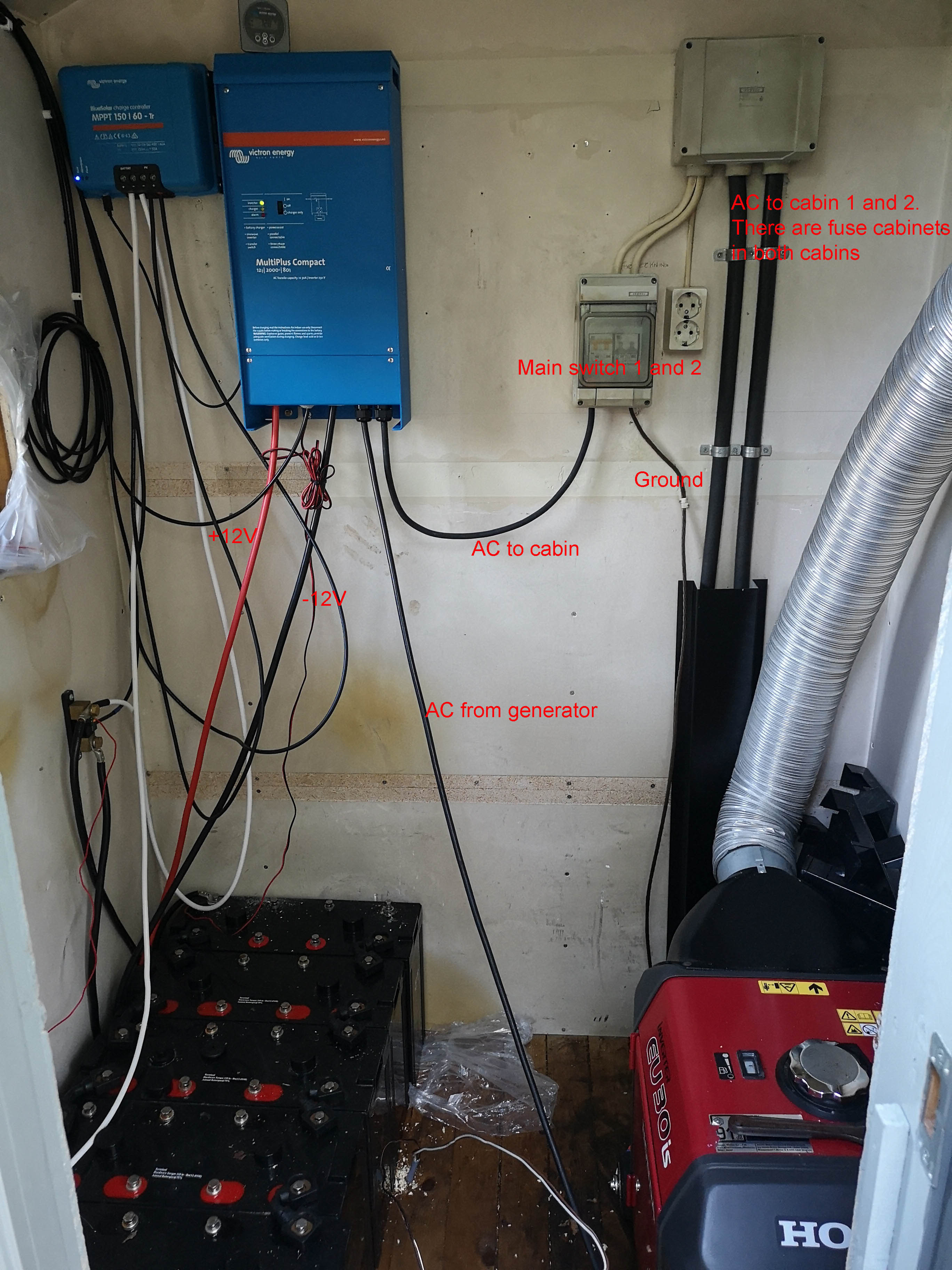
I have a 1000 Ah battery bank and have connected a Victron Multi Compact 12V/2000VA/80 Amp. On the battery poles I get between 50-100 V AC,

When disconnecting everything on the AC side, the AC on DC side dissapears, but hanging a loose 30 meter electric wire to the AC side of the system (wire only, no load), I get 50 V AC. With 300W load, I get about 100 volts.

Wires are 35 mm2 and the device is properly grounded.

1: Any idea what is wrong?

2: Will this dammage my batteries?

Hoping for answer :-)

AC PV Couplingvictron productsbattery system voltagedc systemac out 2
15 comments
2 |3000

Up to 8 attachments (including images) can be used with a maximum of 190.8 MiB each and 286.6 MiB total.

Elimac avatar image Elimac commented ·

Can you make a schematic with all connections and devices involved? This is very strange... are you sure you measured correctly (right scale) and it is not 100mV ?

0 Likes 0 ·
frithjof-plahte avatar image frithjof-plahte Elimac commented ·

Setup is very simple. 6x2V batteries in series giving a 1000 Ah 12V battery bank. two 35mm2 cables to inverter. 10 mm2 230V cables to fuse cabinet. Voltage on batteries in range from 50 to 110 volts, enough to feel the voltage when I touch batteries with my finger (it almost hurts). There are also cables coming in from a Honda Generator (not running). There is also a solar panel giving extra charge. I can go back to the cabin and take pictures tonight.


When disconnecting AC cables directly on the inverter, the AC ripple dissapears.

When attaching the fuse cabinett, it reappears even if all fuses are off. I therefore tested with a 30 meter long cable with open end (nothing attached) This gave 50 Volt AC on batteries

I have also tried disconnecting ground wire and removing solar panel MPPT charger without any change.

0 Likes 0 ·
frithjof-plahte avatar image frithjof-plahte Elimac commented ·

Thank you for helping by the way :-)

Is this bad for the batteries or OK since the current is low?

0 Likes 0 ·
frithjof-plahte avatar image frithjof-plahte Elimac commented ·

I have taken home the Victron and have made a very simple setup with a new battery connected to Victron, nothing else attached.

1: Inverter switched of: 0 volt AC on the battery poles

2: Nothing attached except 0,5 meter cable on AC side: 1 volt AC on the battery poles

3: 30W led light attached with 1 meter cable on AC side: 5 volts ACon the battery poles

4: Nothing attached except 10 meter cable on AC side: 10 volt AC on the battery poles

5: 30W led light attached with 10 meter cable on AC side: 12 volts AC on the battery poles

0 Likes 0 ·
wkirby avatar image wkirby ♦♦ commented ·

Are you sure hat all of yourFC sude connections are good? Are all of the links between the cells connected well?
It seems like you have a poor / high impedance connection somewhere on your battery bank.
A full schematic of you system would help us too.

0 Likes 0 ·
frithjof-plahte avatar image frithjof-plahte wkirby ♦♦ commented ·

Thank you for your reply. I will try to check connection between batteries tomorrow. I can also try to connect a 12 V regular battery.

0 Likes 0 ·
frithjof-plahte avatar image frithjof-plahte wkirby ♦♦ commented ·

I have now tried tightening all connections and even with a different 12V battery. same result, but the voltage on batteries is down to about 30V AC.

I have taken it home from the cabin and thought I would give it a last try before sending to repair. I have connected battery and a simple load, but now it will not switch on. Can it be because the remote control panel is disconnected? Is there a dip switch to tell it that it has no remote?

0 Likes 0 ·
k-k avatar image k-k frithjof-plahte commented ·
Your batteries look like a type 4 * 2V in one block. It seems to be you are using the outer cells in series. 2 different 12V sets in series means 24V. It is not uncommon to have 29 or 30V on a fully loaded 24V system.


What is the name/brand/type of your batterie?

What is the PV-voltage of your system?

Does a PV gain of 300W fit ~70V (pulsed by MPPT) plus 30Vdc from batterie-bank sounds like 100V.

Please make a sketch/scheme of the wiring. (Handwritten doesn't matter)

And please, please switch all off and let if off. Dont touch with bare fingers.

Get someone (4 eyes princip) for tests like is that black cable really this black cable on the other side of the wall.

Are you nearby Grimeton? Are they sending?


0 Likes 0 ·
frithjof-plahte avatar image frithjof-plahte commented ·

I found manual and have made the inverter work without remote panel.

I have now made a very simple setup with a new battery connected to Victron, nothing else attached.

1: Inverter switched of: 0 volt AC on the battery poles

2: Nothing attached except 0,5 meter cable: 1 volt AC on the battery poles

3: 30W led light attached with 1 meter cable: 5 volts ACon the battery poles

4: Nothing attached except 10 meter cable: 10 volt AC on the battery poles

5: 30W led light attached with 10 meter cable: 12 volts AC on the battery poles

0 Likes 0 ·
Elimac avatar image Elimac frithjof-plahte commented ·

1. What instrument are you using? Did you try different instrument? If you can get an oscilloscope it would be ideal.

2. Do you have any common ground? That is, is the neutral on AC side connected by any chance to the (-) of battery?


0 Likes 0 ·
frithjof-plahte avatar image frithjof-plahte Elimac commented ·

I have tried two different regular voltmeters. Unfortunately I do not have a ocilloscope. when it is at the worst, i get an electric shock touching the batteries, so there is definately something wrong.

I have not have common ground. with the current setup in the garage, I only have 1 battery connected to the victron and load directly connected to the AC out. Can I connect the two ground cables without any risk?

0 Likes 0 ·
Elimac avatar image Elimac frithjof-plahte commented ·

No, better don't do it.

It's hard to give good advice at a distance. It seems to me there is something seriously wrong wither with the equipment or the setup. To get a chock on DC side is certainly not good, and if the ripple is in deed as high as you state, it is also not good for the batteries. Could be dangerous in my opinion! Try to find good engineer near by and check localy. If you insist, you can try complete this thread with more information, but my 2 cents is that you should stop using the system untill this is sorted out.

Any powerfull radio station (MW) near by ?

0 Likes 0 ·
frithjof-plahte avatar image frithjof-plahte Elimac commented ·

Thank you. I will send it to Victron for repair :-)

0 Likes 0 ·
boekel avatar image boekel ♦ frithjof-plahte commented ·

Hi @Frithjof Plahte

That's not a good plan, you should get an experienced technician to your system because the things you're measuring are most likely due to installation errors. Sending the unit to Victron will -probably- not help you.

Further I urge you to have the whole system re-wired by a technician (electrician / installer / ...).

0 Likes 0 ·
Elimac avatar image Elimac frithjof-plahte commented ·

If you measure variable AC depending on wire lenght, that does not point to inverter problem at first glance. Please ask someone to check the installation first.

I had in the past some AC that penetrated other systems and it turned out to be a powerful Medium Wave radio station. But nothing in the order of 100V, it was mV. And it was not 50Hz.

If were you, I would get an oscilloscope first and check the wave shape, amplitude and frequency prior to jumping into conclusions.

0 Likes 0 ·
5 Answers
Guy Stewart (Victron Community Manager) avatar image
Guy Stewart (Victron Community Manager) answered ·

Hello Frithjof,

There are many safety issues I can see from the picture you have posted, including:

  • no DC fuses or circuit protection,
  • generator next to batteries,
  • unsecured wires,
  • uncovered batteries with exposed terminals below equipment,

This is not a safe installation, and needs a professional electrician or technican with Victron training to make it safe.

Please turn it off, and get help from a professional to work on the installation.

2 |3000

Up to 8 attachments (including images) can be used with a maximum of 190.8 MiB each and 286.6 MiB total.

Stuart avatar image
Stuart answered ·

As an electrical engineer and an installer of high energy plant including switchgear for the London underground I have to agree 100% with Guy from Victron. Not including the valid issues that Guy has mentioned I am also unsure about the cable gauge being used.


The ground termination depending on your installation type IE how earth/neutral is terminated. If you are using SWA and the external insulation is compromised you may well have a low resistance path via the ground return.


I would point out that I am not an expert on Victron inverters I can only go by what I can see in the attached image and your description. If I was called in to perform an EIC I would fail that installation. Your earth conductor for example looking at the diameter would not have a sufficiently low impedance to carry full fault current.


For the sake of your liability I would strongly recommend you have a written report completed by a qualified electrical engineer. I do not know the legal and liability implications for your country of installation but in the UK the last engineer to perform any work on an installation is fully liable for any fire, damage or injury caused. I agree with Guy and very strongly recommend you shut down the system and have an independent inspection completed.


Nothing is worth serving time in prison for !!!

2 comments
2 |3000

Up to 8 attachments (including images) can be used with a maximum of 190.8 MiB each and 286.6 MiB total.

frithjof-plahte avatar image frithjof-plahte commented ·

Thank you. I have allready removed inverter from the system, and tried to connect the Victron to a new battery on the work bench. Without anything else attached, I get 1 V AC on battery. If I connect a 10 meter extention cable (cable only, nothing else attached) to AC side, I get about 11 volts AC on battery. I do not understand that there can be anything wrong with setup...

0 Likes 0 ·
boekel avatar image boekel ♦ frithjof-plahte commented ·

How are you measuring this? from where to where?

0 Likes 0 ·
Stuart avatar image
Stuart answered ·

That leaves only one explanation as there is no way any radio transmission could induce AC at that those voltages. I would double check your connections and ensure you do not have a bridged connection to neutral or ground. If all connections are correct then I can only surmise that you have a faulty inverter.


It may be worth consulting with the Victron staff on this forum or Victron technical support directly but it sounds very much like a faulty unit. I would arrange for a return to Victron for testing and once you have rectified the installation wiring you can then put the unit back into service.

2 |3000

Up to 8 attachments (including images) can be used with a maximum of 190.8 MiB each and 286.6 MiB total.

mikeb avatar image
mikeb answered ·

Hi


I agreed with guy on this install some work needs to

Be done to bring it up to a satisfactory serviceable condition.


Some notice needs to be taken on the comments advising you of this


Regards

Mike


I notice there is a black cable going in to the multi which you haven’t labelled what that ?

2 |3000

Up to 8 attachments (including images) can be used with a maximum of 190.8 MiB each and 286.6 MiB total.

k-k avatar image
k-k answered ·

Why do i see this on top in 2023?

Question are, shown for me, from 2019.

1 comment
2 |3000

Up to 8 attachments (including images) can be used with a maximum of 190.8 MiB each and 286.6 MiB total.

Justin Cook avatar image Justin Cook ♦♦ commented ·
Because someone else just commented recently, so it moved to the "top" of the list.
0 Likes 0 ·