question

v-andi avatar image
v-andi asked

MP2 GX + REC-BMS + Tesla: keine Erfahrung und Riesenproblem

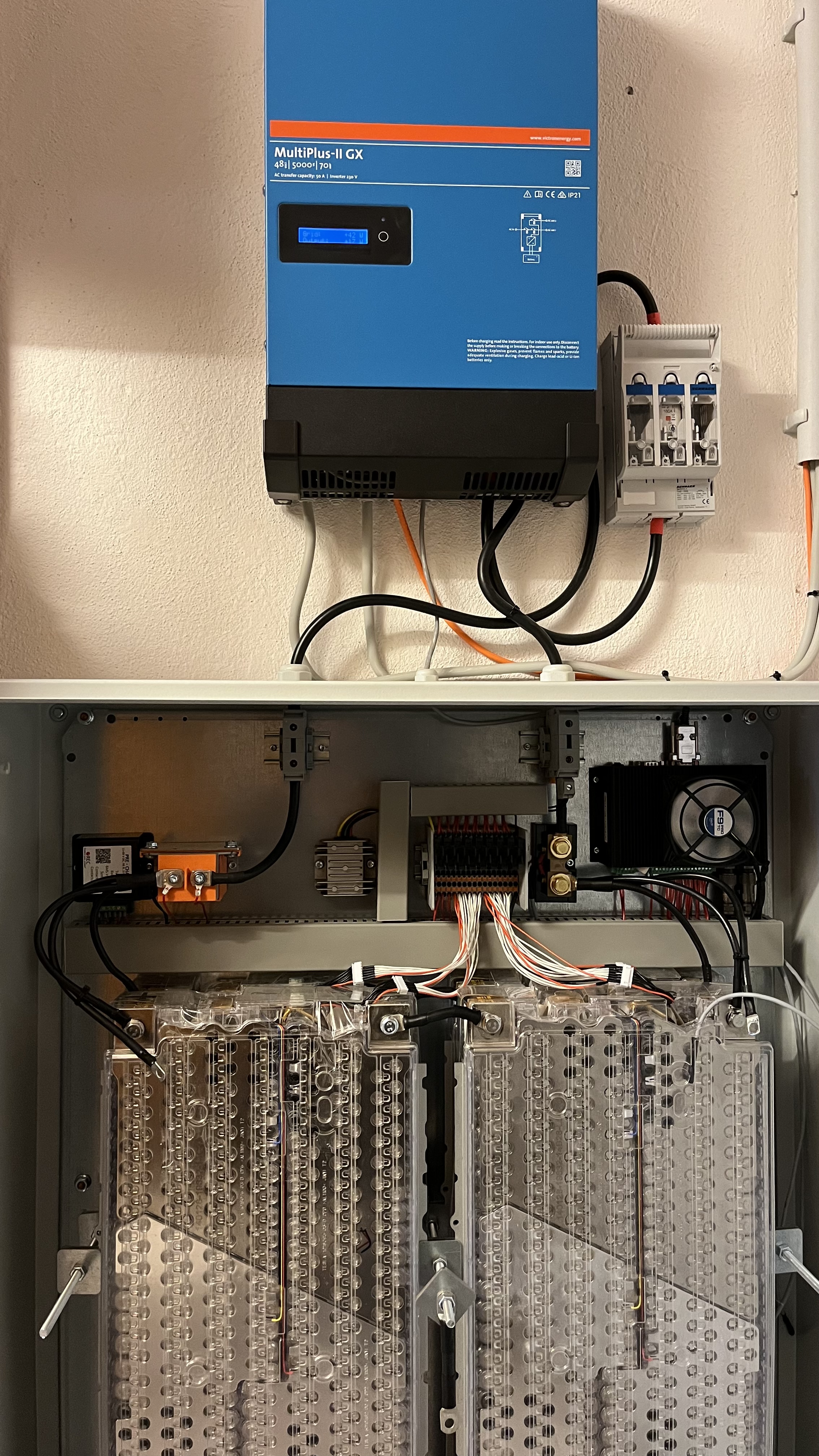
Die Anlage von einem Bekannten klappt nicht richtig (die Firma gibt keinen Support mehr).

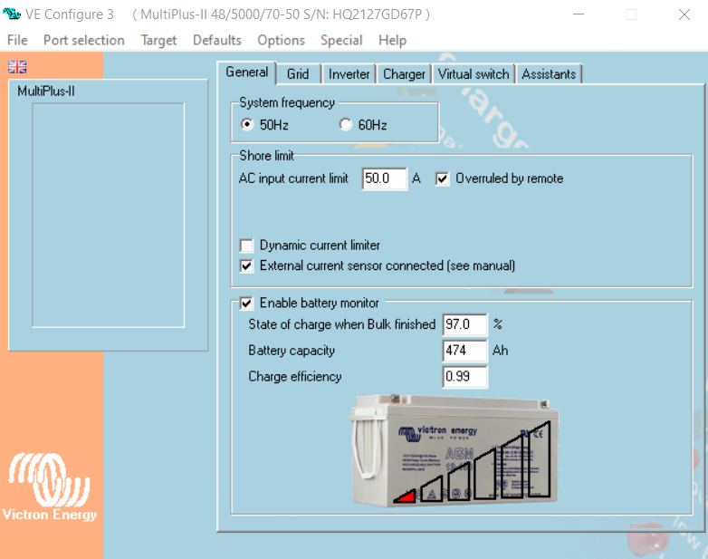
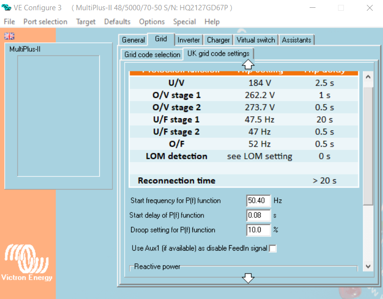
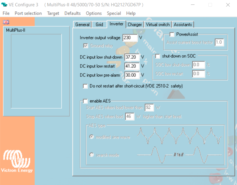
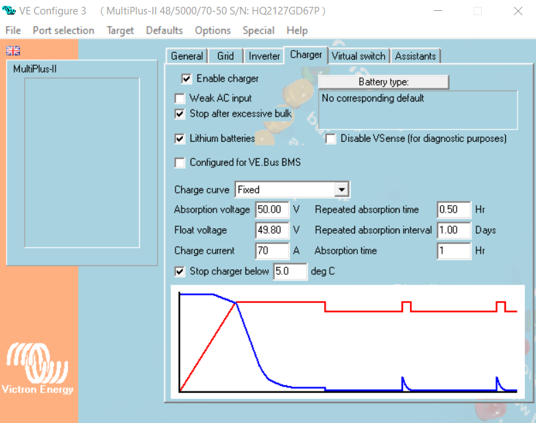
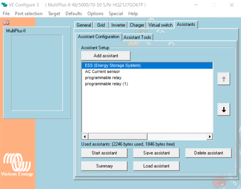
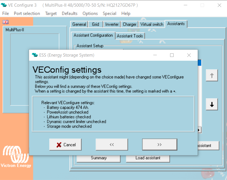
Der MP steht auf "externe Steuerung", das REC ist korrekt verkabelt und online. Der Akku steht auf 80% und ist nach 5 Minuten auf 2% runter. Beim Laden gibt das REC schon bei 47,3V "Spannung hoch" Alarm an den Victron.

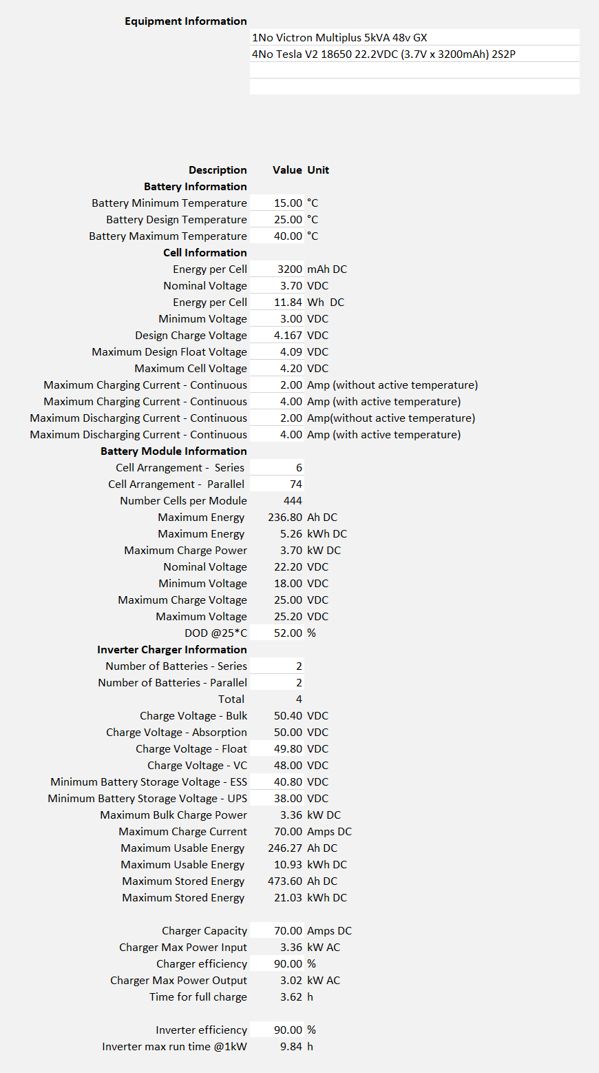
Meine erste Vermutung: Der Tesla-Akku ist hinüber, dann wären aber alle 4 Packs hinüber. Oder das BMS ist so falsch eingestellt, dass der den Akku nicht lädt.

Leider habe ich keine REC-Software und kein Kabel.

Wie könnte ich vorgehen?4dba7146-44df-4ef0-9126-55cf1fee4a14.jpeg

Multiplus-IIESSBMS
2 |3000

Up to 8 attachments (including images) can be used with a maximum of 190.8 MiB each and 286.6 MiB total.

5 Answers
holger Bleckwehl avatar image
holger Bleckwehl answered ·

Ich vermute eher einen Fehler im BMS, da werden falsch/keine Werte übertragen...

und gefühlt sind die AKKU Kabel auch recht dünn ??

2 |3000

Up to 8 attachments (including images) can be used with a maximum of 190.8 MiB each and 286.6 MiB total.

netrange avatar image
netrange answered ·

Wie es aussieht , ist da nur 1 BMS für alle 4 Akkus zuständig?!?

Eine Sytemzeichnung zum Problemkind wäre super ... Man kann leider nicht ALLES aus dem Photo erschließen .

Super wären auch technische Daten zum Speicher und Screenshots von der Multiconfiguration.

Wie ist der MP in der Hauselektrik eingebunden?

Soll viele Fragen ;)

6 comments
2 |3000

Up to 8 attachments (including images) can be used with a maximum of 190.8 MiB each and 286.6 MiB total.

v-andi avatar image v-andi commented ·
Leider gibt es keine Zeichnung.


Akku aus Model-S, 4 x 4,4kwh macht 17,6kwh.

EM24 in HVT.

2 Fronius WR, vernetzt.

FritzBox.


Wie könnte man den Fehler eingrenzen?


0 Likes 0 ·
netrange avatar image netrange v-andi commented ·
Wieviel Zellen hat 1 Akku ???

Weil nur 1 BMS zu sehen ist !!!

0 Likes 0 ·
v-andi avatar image v-andi netrange commented ·

Die "normalen" Akkus aus Tesla S-60 mit 6 Zellen je Pack. 2 Packs in Reihe für 45,6V nominal.

Nur 1 BMS.

0 Likes 0 ·
netrange avatar image netrange v-andi commented ·

Alles klar, das macht Sinn.

Ich würde erstmal die Packs abklemmen und ein paar Minuten später die Leerlaufspannung messen. Da du einen 2s/2p Akku hast , genügt schon eine defekte Zelle und deine Spannungsversorgung ist hin.

Dazu kommt noch das die unterste Spannung für den MP2 bei 38V liegt.

Steigt jetzt eine Zelle aus und dann noch unter Last schaltet dein Multi wahrscheinlich schon aus.

Da ist noch ein Trennrelais und ein Shunt drin. Das BMS selbst übermittelt wohl keine Werte...

Eine Systemzeichnung wäre halt super.

Zur Fehlersuche von hier aus recht schwierig.

Zeige uns mal bitte die Config aus VE Config in ein paar Bildern

0 Likes 0 ·
v-andi avatar image v-andi netrange commented ·
Wie kann man die externe Steuerung ausschalten?

in der Remote Konsole kann ich den Punkt auswählen, aber nicht ändern.

0 Likes 0 ·
netrange avatar image netrange v-andi commented ·
das mit der ext. Steuerung bei Nutzung von ESS ist völlig normal ...Sorry mein Fehler ... ich war im Bereich ESS unterwegs. da gibt es auch den Menüpunkt "extern"


Akkus abklemmen und erstmal die Spannung messen um sich einen Eindruck zu verschaffen.


0 Likes 0 ·
Jason - UK avatar image
Jason - UK answered ·

@V-Andi I have the same batteries and Multiplus unit. Im running my without a proper BMS. I'm actually using a 2 wire 'BMS' interlocked with over voltage and under voltage relays. Because of that, all of the settings for setting the charge rate, float voltage and cut off voltage are done in the Multiplus GX.

Feel free to look at the photos on the below link and how the system is operating in the advanced information display. I need to update the photos as I am keeping the batteries warm using the heating coil which is much needed on the tesla batteries if they get too cold.

If its of interest, I'll send you my EV Configure settings so you can compare?

https://vrm.victronenergy.com/installation/171934/share/db6807bb


1 comment
2 |3000

Up to 8 attachments (including images) can be used with a maximum of 190.8 MiB each and 286.6 MiB total.

v-andi avatar image v-andi commented ·
This looks correct. Better than mine. Please give me a list of the material and a photo from the "BMS". I want to help my fried….

And screenshots EV Configure

Many thanks

1 Like 1 ·
Jason - UK avatar image
Jason - UK answered ·

@V-Andi noting that I am in the UK so some setting may differ from your location.

1675869011259.png

1675869068606.png

1675869124601.png

1675869153059.png

1675869173999.png

1675869220766.png


1675869011259.png (137.3 KiB)
1675869068606.png (117.2 KiB)
1675869124601.png (142.0 KiB)
1675869153059.png (106.6 KiB)
1675869173999.png (93.5 KiB)
1675869220766.png (116.2 KiB)
1 comment
2 |3000

Up to 8 attachments (including images) can be used with a maximum of 190.8 MiB each and 286.6 MiB total.

Jason - UK avatar image Jason - UK commented ·

@V-Andi Below is the data I started with before the install to work out a basic level of performance I was to expect. Its been a while since I made these notes so please take then as draft but it might help you with anything that might assist you.

1675871841941.png

0 Likes 0 ·
1675871841941.png (141.4 KiB)
v-andi avatar image
v-andi answered ·

Thank you Jason. Please show me your BMS for shut down. It is the best way i think.

1 comment
2 |3000

Up to 8 attachments (including images) can be used with a maximum of 190.8 MiB each and 286.6 MiB total.

Jason - UK avatar image Jason - UK commented ·

@V-Andi on my 2-wire BMS, I have adjustable relays set to 36v for under voltage protection on each cell pack and a relay set to 50.4v for over-voltage protection on each sell pack. Both purchased on eBay, resistor to provide the adjustment to 50.4v for over voltage protection. This arrangement breaks the NC (Normally closed) 2 wire control to the Multiplus. Also included into this 2 wire arrangement is a smoke and heat alarm / sensor as my batteries are located in the garage below a bedroom. Both these alarms have relay bases to break the 2 wire in the event of a alarm activation.

As I have a pumped coolant / heating supply though the batteries, I use the single temperature sensor provided with the Multiplus to record the temperature of the coolant / heating fluid being pumped thought the batteries. The sensor is clamped to the pipe work on the return from the batteries. Even with the summer we had where it hit 40*C here in the UK, by batteries never went above 32C which is fine for the batteries so the cooling park of the loop is basically unused. I have a 150w immersion element connected to the 240v mains supply in the garage. The immersion element on the flow which runs when the air temperature drops below 16 and the heating loop drops below 30*C. The temperature senor connected to the Multiplus stops the inverter charger if it drops below 5*C.

The above arrangement doesn't stop the inverter if a single group of cells over-volt. The 2 wire only works if the pack over / under volts.

I'll take some photos when I have a moment of the current set up and post them on here.

1 Like 1 ·