question

andrebotha avatar image
andrebotha asked

ESS NOT feeding back to grid

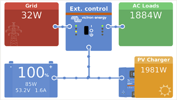
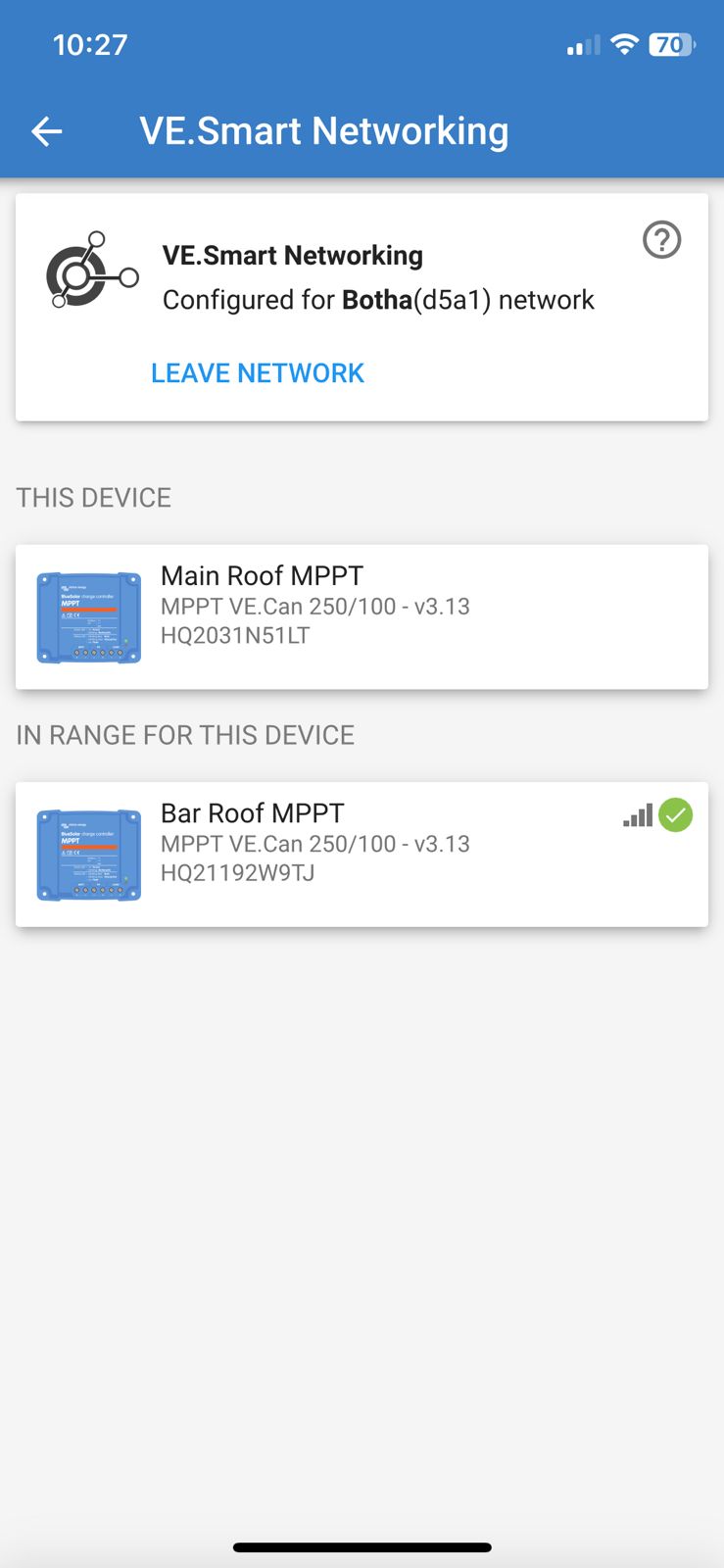
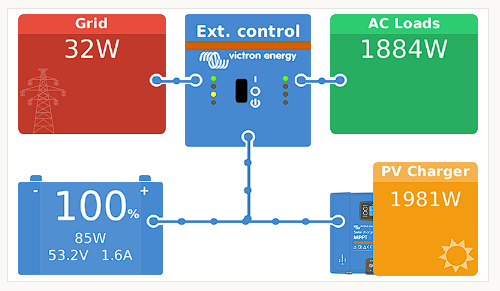
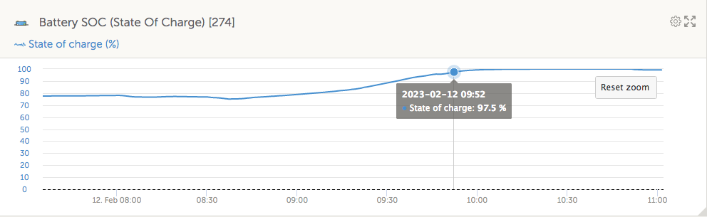
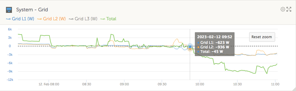
HI All, I'm having an issue where my system is not feeding back to the grid anymore (batteries are at 100%). I have two PV charge controllers one with 16 panels and the other with 4. It seems what is happening is that the PV controllers are limiting power produced to match what my AC loads are using. When I switch more electronics on the PV ramps up so its not a fact that I cannot produce more power. I have 6.6KW worth of panels.

ess-settings.pngdashboard.png

ESS
ess-settings.png (35.4 KiB)
dashboard.png (50.8 KiB)
46 comments
2 |3000

Up to 8 attachments (including images) can be used with a maximum of 190.8 MiB each and 286.6 MiB total.

marekp avatar image marekp commented ·

@AndreBotha

Today I observed MPPTs turning off when battery gets to absorption.

After ca 10 minutes they started producing again.

screen-shot-2023-02-12-at-111041-am.png

screen-shot-2023-02-12-at-111154-am.png

screen-shot-2023-02-12-at-111317-am.png

screen-shot-2023-02-12-at-111421-am.png

screen-shot-2023-02-12-at-111453-am.png

screen-shot-2023-02-12-at-111511-am.png

screen-shot-2023-02-12-at-111545-am.png


1 Like 1 ·
peregrines avatar image peregrines marekp commented ·
I have the same problem :(

Did you find a solution?

0 Likes 0 ·
nickdb avatar image nickdb ♦♦ commented ·
You are going to need to provide a lot more detail about your system, it's components and configuration.

There is nothing to go on here and crystal balls use too much power ;)

Are any limits set in DVCC?

Is DC feed-in actually enabled in ESS?

0 Likes 0 ·
andrebotha avatar image andrebotha nickdb ♦♦ commented ·

Sorry about that. Not sure what information required. Happy to share all settings you guys would need.


I have Victron 5KW inverter with two charge controllers and 3 Dyness B3 batteries.
No limits on DVCCdvcc.png
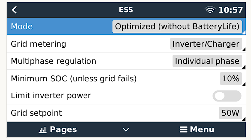
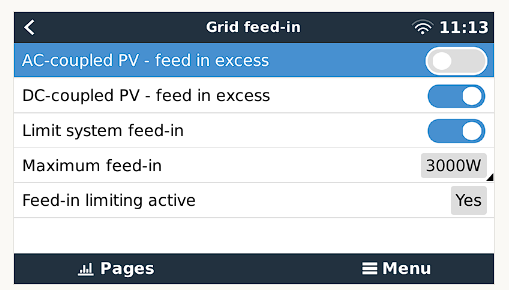
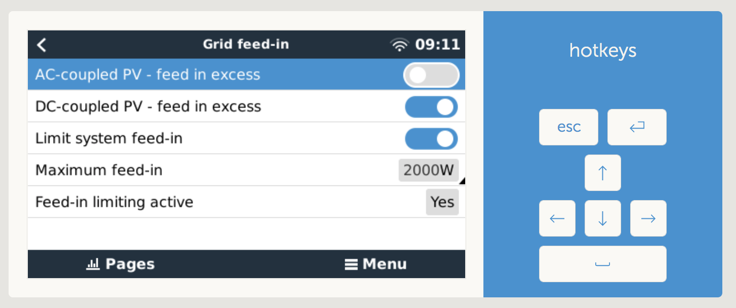
ESS settings are enabled, there use to be no limit but i enabled one to test and no change.

feed-in.png

0 Likes 0 ·
dvcc.png (36.2 KiB)
feed-in.png (32.6 KiB)
gazza avatar image gazza commented ·

Did it feed back before... or is it a new system?

0 Likes 0 ·
andrebotha avatar image andrebotha gazza commented ·
It use to feed back. But towards end of last year it stopped.


0 Likes 0 ·
gazza avatar image gazza commented ·

Did it coincide with any firmware update?
Are you sure you have feed in (DC or AC pv) enabled?
ess-grid-feed-in.png

0 Likes 0 ·
ess-grid-feed-in.png (127.1 KiB)
andrebotha avatar image andrebotha gazza commented ·

So my system is set to not automatically update any software. I cannot remember if it was after an update as i only realized it now. We are only getting some decent summer sun now so I've been monitoring it more.


Ive also had both those settings enabled. But im sure its DC because when batteries are being charged by solar it does a straight pass through, and not through my inverter. Only when it gets charged from grid does it run through inverter.

0 Likes 0 ·
gazza avatar image gazza andrebotha commented ·
Yea sorry I re-read your post and you mention 2x charge controllers so it is DC
0 Likes 0 ·
andrebotha avatar image andrebotha commented ·

I have also updated the PV controllers, ESS and the inverter to the latest software to see if that would help but still the same.

0 Likes 0 ·
nickdb avatar image nickdb ♦♦ andrebotha commented ·

If you set a negative grid setpoint does it feed-in?

0 Likes 0 ·
andrebotha avatar image andrebotha nickdb ♦♦ commented ·
If i set negative it does feed back but then it uses battery to push back to the grid, so that is not a solution really.
0 Likes 0 ·
nickdb avatar image nickdb ♦♦ andrebotha commented ·

@AndreBotha It's just a test.

Turn off SVS in DVCC and try again.

Make sure all your devices are communicating and the BMS is sending CVL etc.

0 Likes 0 ·
gazza avatar image gazza commented ·

It may seem trivial but I would probably do a complete reboot of the system. If that doesn't get you back to "where you were" when it worked then I would look at all the settings in VE Configure 3, just as you would have done when you set up ESS.

0 Likes 0 ·
andrebotha avatar image andrebotha gazza commented ·
I have rebooted the system completely. My next step would be to just reset the system to default and do all the settings again. Just wondered if anyone would have any ideas before i get to that..
0 Likes 0 ·
andrebotha avatar image andrebotha commented ·

So i have double and triple checked all the settings on the inverter itself and its all correct. I suspect that the Nov/December update on the charge controllers are at fault here. I have reached out to the Victron SA representative now to find out from them if they are aware of a software bug. If not then i will revert to 3/4 versions back on the charge controllers to see if that changes anything. I will post an update once i have heard back with more information.

Thanks so far for the comments.

0 Likes 0 ·
Alexandra avatar image Alexandra ♦ andrebotha commented ·
@AndreBotha

Part of the system was updated. The rest will need to be updated to match.

The 'bug' may not be a bug so kuch as be the old and new don't play nice together.

0 Likes 0 ·
andrebotha avatar image andrebotha Alexandra ♦ commented ·
Currently everything is new or on latest firmware versions. But i hear you. Just don't have any other options as I don't know where the issue is..
0 Likes 0 ·
nickdb avatar image nickdb ♦♦ andrebotha commented ·
Disable SVS as I have suggested. It shouldn't be on and can cause issues.

Should be an easy test.

0 Likes 0 ·
andrebotha avatar image andrebotha nickdb ♦♦ commented ·
Think you missed my reply to that. I have disabled and restarted. Didn't make any difference.
0 Likes 0 ·
nickdb avatar image nickdb ♦♦ andrebotha commented ·

Ok. It is worth checking what the BMS is sending as it's CVL and comparing that to what the mppts/inverter are reporting (and measuring it with a meter).

Loss or a bad reference can cause issues, hence disabling SVS.

You don't mention which mppts they are, but there isn't anything in current updates that is known to cause issues.

0 Likes 0 ·
andrebotha avatar image andrebotha andrebotha commented ·

Just a follow up with where I am right now. Victron SA responded and told me that it seems that one of the three Dyness B3 batteries that I have is out of sync. This is possibly caused by the BMS on the batteries. I'm now trying to see if I can get the company that I purchased these batteries to see if they can update the BMS for me. @Dyness perhaps you can assist with this? These batteries were bought on 2020/09/29, so in my opinion, I should not have any issues with them this early in their life span.

0 Likes 0 ·
Alexandra avatar image Alexandra ♦ andrebotha commented ·
@AndreBotha

You could verify that it is the bms, by removing comms (mppts will have to be reset up you will probably see error #67)

And let it run like that. See if it feeds back like that when there is excess.

Maybe cap the charged voltage in DVCC.

What h the battery voltage while doing that though. Usually an imbalance causes voltage rise.

0 Likes 0 ·
dyness avatar image dyness andrebotha commented ·

@AndreBotha

Hi Andrebotha, really sorry for the inconvience you have faced now.

Sure, it is our responsibility to help customers solve problems encountered in the use of products. Could you please conatct us via the email service@dyness-tech.com?Our after-sales team will provide you with technical support and solve the problem as soon as possible.

0 Likes 0 ·
marekp avatar image marekp commented ·

@AndreBotha

In this situation there will not be any feeding because there is noting to feed.

screen-shot-2023-01-13-at-110546-am.png

0 Likes 0 ·
andrebotha avatar image andrebotha marekp commented ·
No there is definitely more than enough power to feed back. When turn my microware on or aircon the AC loads go up and then the PV power goes up. The issue seems that the PV is only producing enough power to run my AC loads. When my batteries need charging i will produce 5000w+ on PV to charge batteries and run AC. As soon as batteries are 100% the PV drops down and does not push back to the grid.
0 Likes 0 ·
marekp avatar image marekp andrebotha commented ·
0 Likes 0 ·
andrebotha avatar image andrebotha marekp commented ·

Looking at it, it almost seems the same. Ill have 1 charge controller switching off completely because the other one is producing enough power to supply AC and with spikes it will switch on for a bit. When AC increases both will turn on but one will not run at full power. I definitely think this is a bug in the Charge Controller software, and similar to you it does not push back to the grid.

They are suppose to not push back to grid when there is no power coming in from grid. But its acting like that all the time it seems.

0 Likes 0 ·
marekp avatar image marekp andrebotha commented ·

@AndreBotha

I thing this "bug" is in the GX because it is GX that externally controls MPPT.

Did you try reboot GX?

In my system after GX Reboot, both MPPTs start feeding.

Can you show us the SOC graph and MPPT graph, same as I posted?

Since you are using "inverter/charger" as a grid meter make sure that internal CT is working properly.

In new MP-II units there is no external CT 3.5mm socket because it was replaced with terminal block. This is Victron's response to the failing contact on the 3.5mm external CT socket.

Most of the time plugging and unplugging 3,5mm jack many times can fix the contact.

https://community.victronenergy.com/questions/155992/current-sensor-port-on-mp2.html

1 Like 1 ·
gazza avatar image gazza andrebotha commented ·
It is looking like a BMS related issue.. since that is the "external" control.?
0 Likes 0 ·
marekp avatar image marekp gazza commented ·
@Gazza

It is not BMS that "externally" controls MPPT but GX.

0 Likes 0 ·
nickdb avatar image nickdb ♦♦ marekp commented ·
The gx relays the instructions sent by the bms, so yes it is bms related. It all seems to work with supported batteries and bms’s, that isn’t a coincidence.
0 Likes 0 ·
marekp avatar image marekp nickdb ♦♦ commented ·

@nickdb

But what GX relays if BMS does not send anything as it is in "2 signal BMS"?

My BMS is not sending anything to GX but GX turns my MPPTs off when battery switches to absorption.

With "DC-coupled PV - feed in excess" turned ON they should feed the grid and not turn OFF.

0 Likes 0 ·
nickdb avatar image nickdb ♦♦ andrebotha commented ·
Mppt's don't load balance perfectly, also everything is driven by voltage.

I suggested you check voltages manually, and what the BMS CCL broadcast is sending.

If the voltage readings are off (can be caused by cabling or the BMS) then the mppt's will go to sleep.

It is impossible to diagnose something like this via the internet, so whip out your meter and start checking all the readings. Compare to VRM charts.

With SVS on, is the BMS chosen as the reference?

Is the BMS set as the reference in GX system setup?


0 Likes 0 ·
yunus avatar image yunus commented ·

Can you let me know to you solved this. I have the same issue

0 Likes 0 ·
andrebotha avatar image andrebotha yunus commented ·
Still not resolved. :(
0 Likes 0 ·
blackmarlin avatar image blackmarlin commented ·

@AndreBotha I recently found your thread. Do you already have a solution?

I have a similar issue: https://community.victronenergy.com/questions/185963/mppt-power-is-limited-for-dc-feed-in-if-battery-is.html

0 Likes 0 ·
andrebotha avatar image andrebotha blackmarlin commented ·
Unfortunately not, still does not feed back to grid.
0 Likes 0 ·
ejrossouw avatar image ejrossouw andrebotha commented ·

Do you have a CT clamp, ET112 or use the inverter as gridmeter?

0 Likes 0 ·
andrebotha avatar image andrebotha ejrossouw commented ·
Using the inverter as a gridmeter.
0 Likes 0 ·
marekp avatar image marekp andrebotha commented ·

@AndreBotha

Make sure that MP-IIs internal CT is working properly.

Recently Victron changed the way external CT is connected because 3.5mm socket, used before, was failing quite often and when 3.5mm socket fails, internal CT was disconnected.

You are using internal CT as a grid meter.

0 Likes 0 ·
ejrossouw avatar image ejrossouw andrebotha commented ·
Are the MPPT's connected as a smartnetwork? Also, as per Marekp's comment, on some of the MP-IIs it was found the 3.5mm CT socket played up and simply inserting a connector and removing it a few times sorted it. This fault resulted incorrect internal readings. A wildcard, but worth a shot.
0 Likes 0 ·
andrebotha avatar image andrebotha ejrossouw commented ·

Yeah both connected to Smartnetwork.main.jpegbar.jpeg

0 Likes 0 ·
main.jpeg (60.7 KiB)
bar.jpeg (62.0 KiB)
nickdb avatar image nickdb ♦♦ andrebotha commented ·
Remove smart networking, it should not be used in combination with connection to a GX and will only cause issues.
0 Likes 0 ·
andrebotha avatar image andrebotha nickdb ♦♦ commented ·
I removed the smart network but unfortunately the sun ducked soo will only be able to see and test anything on Thursday/Friday this week looking at the forecast.
0 Likes 0 ·
Show more comments
0 Answers