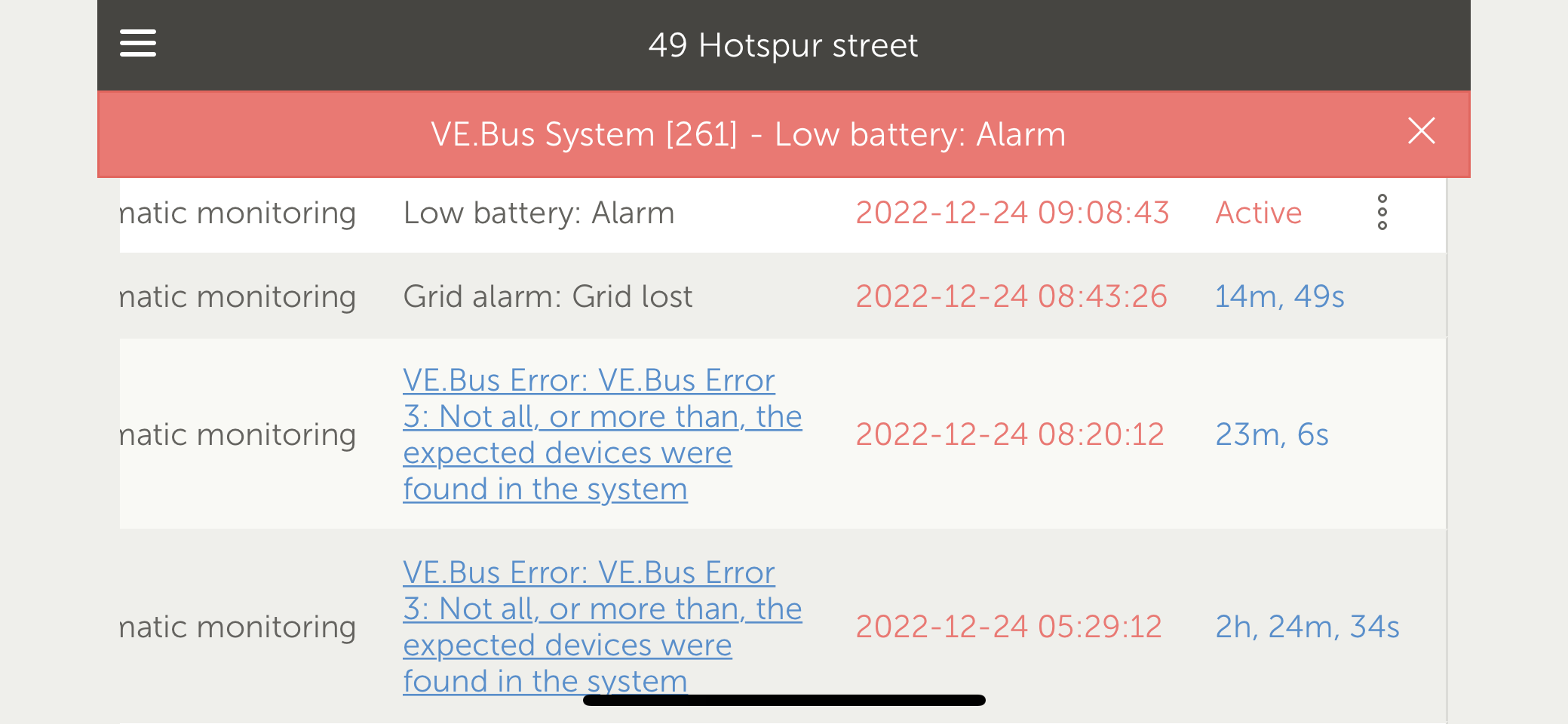
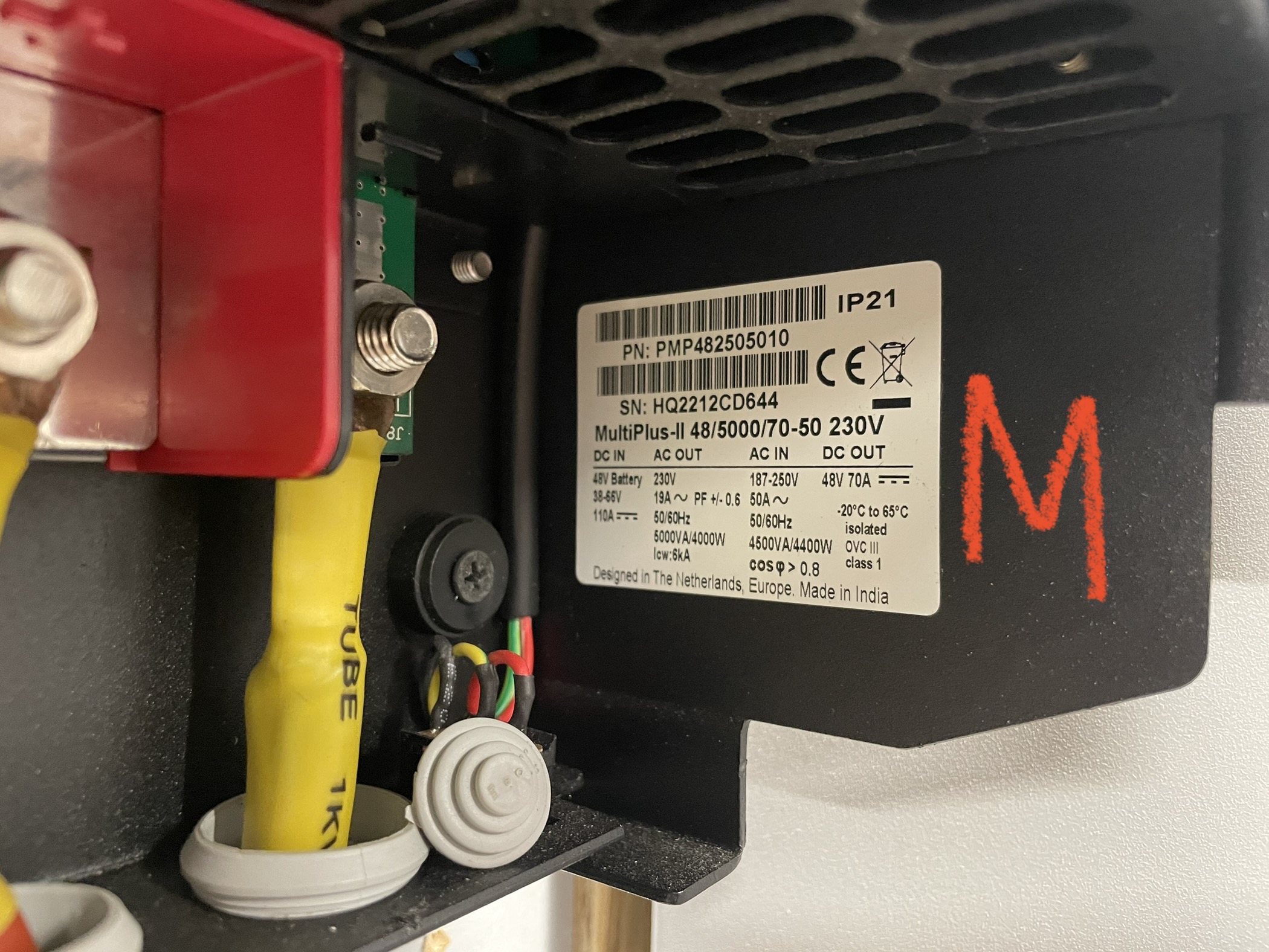
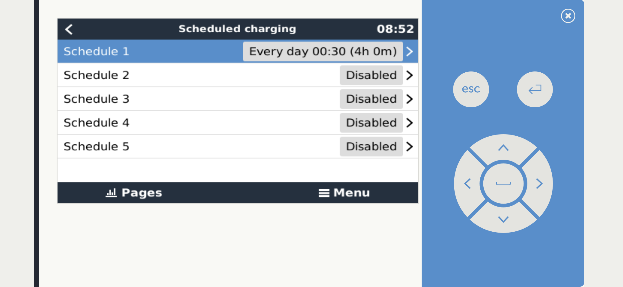
 I had a single multi system working fine connected to my 20kwhs of PylonTech batteries. There wasn’t enough off peak grid available to recharge them from 10% to 100% over night (4hours) so I’ve installed a second Multi. I had multiple error messages last night as I tried to get everything to talk to each other and eventually managed to get it to schedule charge at 00:30. It drew 140amps which put one of my cables up to 102°c so I knocked the input ac amps back to 30amps and this reduced the DC amps to 100amps and the cable temp went down to 60°c, there was no fire risk but do need to look at the connections and / or cable size (25mm). The system recharged the batteries to 100% last night and started up this morning but the returned a #3 error, not all devices… found in the system.…and the. A low battery alarm.The system is saying the multi is not connected.
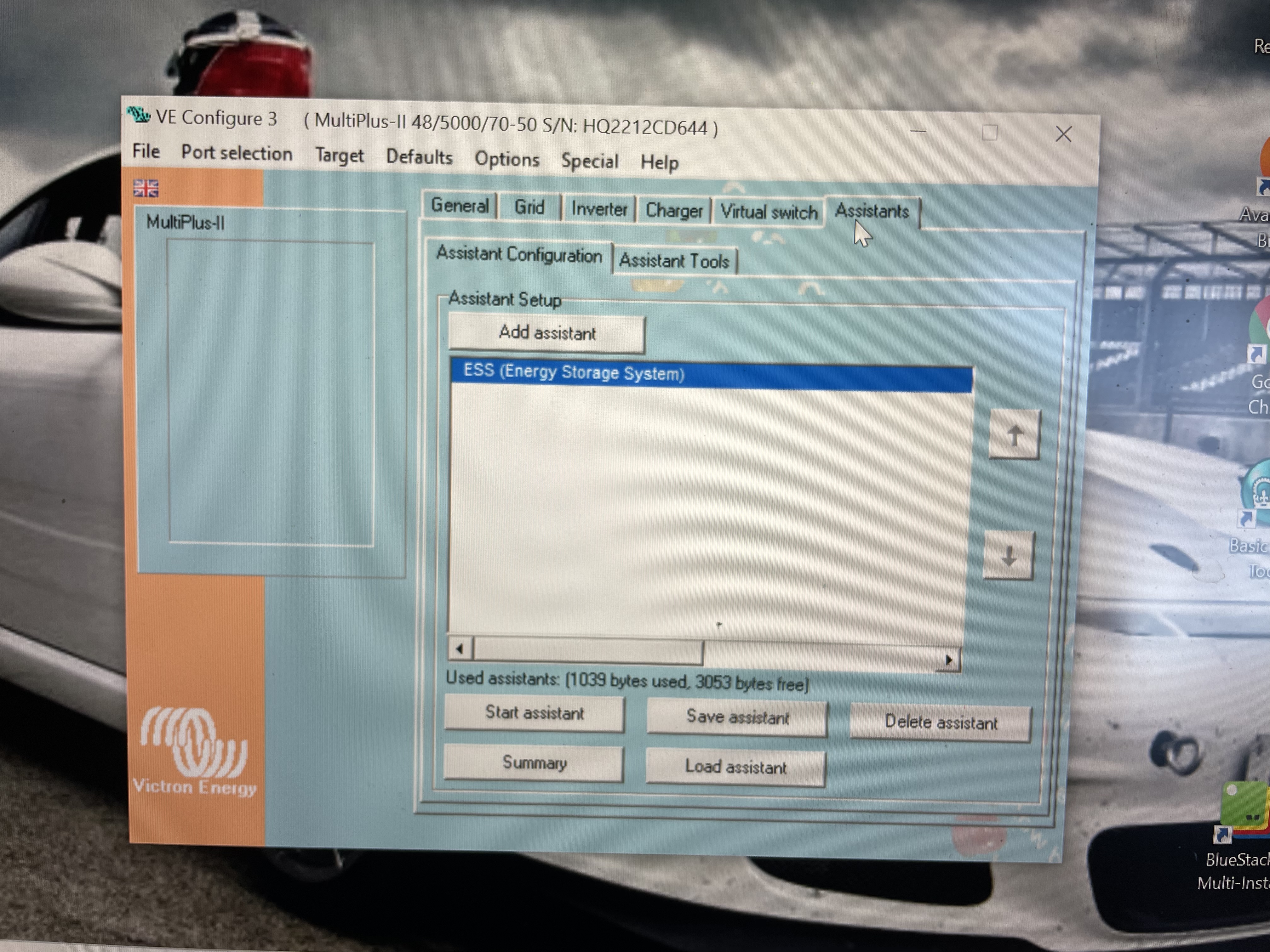
I’ve done a hard reset on the system, even powering down the batteries and it started up with the Master showing the inverting led and the slave flashing the two lights which I presume means it’s working in slave mode but with no output to the AC out 1 which my heat pump is connected onto.- I have read and watched the advanced videos on parallel systems and I did set up the master and slave via VEBus quick setup although I presumed there was only a need for one ESS assistant on the master.
- Any help would be appreciate, thanks.
asked
Multiple issue with parallel (2) Multis on PylonTech battery system.
From previous posts you seem new to these systems and configuring a parallel system is an advanced setup which can go wrong if not done properly.
Before you set fire to something or break something expensive, please get an experienced installer to help you, or contact your supplier for assistance.
There is not enough here to even start and this is not the place for advanced diagnosis.
The 3phase/parallel system setup guide and wiring unlimited doc have good information as does guy's training video
Hi Nick, thanks for your reply. I’m a professional heating engineer, not a punter. I’m venturing into this area of technology in order to be able to decarbonise heating systems at an affordable price point. I’ve been through all the videos and read all of the manuals but will refresh my memory with them again. Thanks Richard.
Cool. Good luck.
When things don’t go to plan go back to basics.
Step through the setup piece by piece.
Check/replace comms cables.
Use a clamp meter to check how even load is spread between them.
You have access to the ve bus monitor via a mk3 adapter, that can also give some insights.
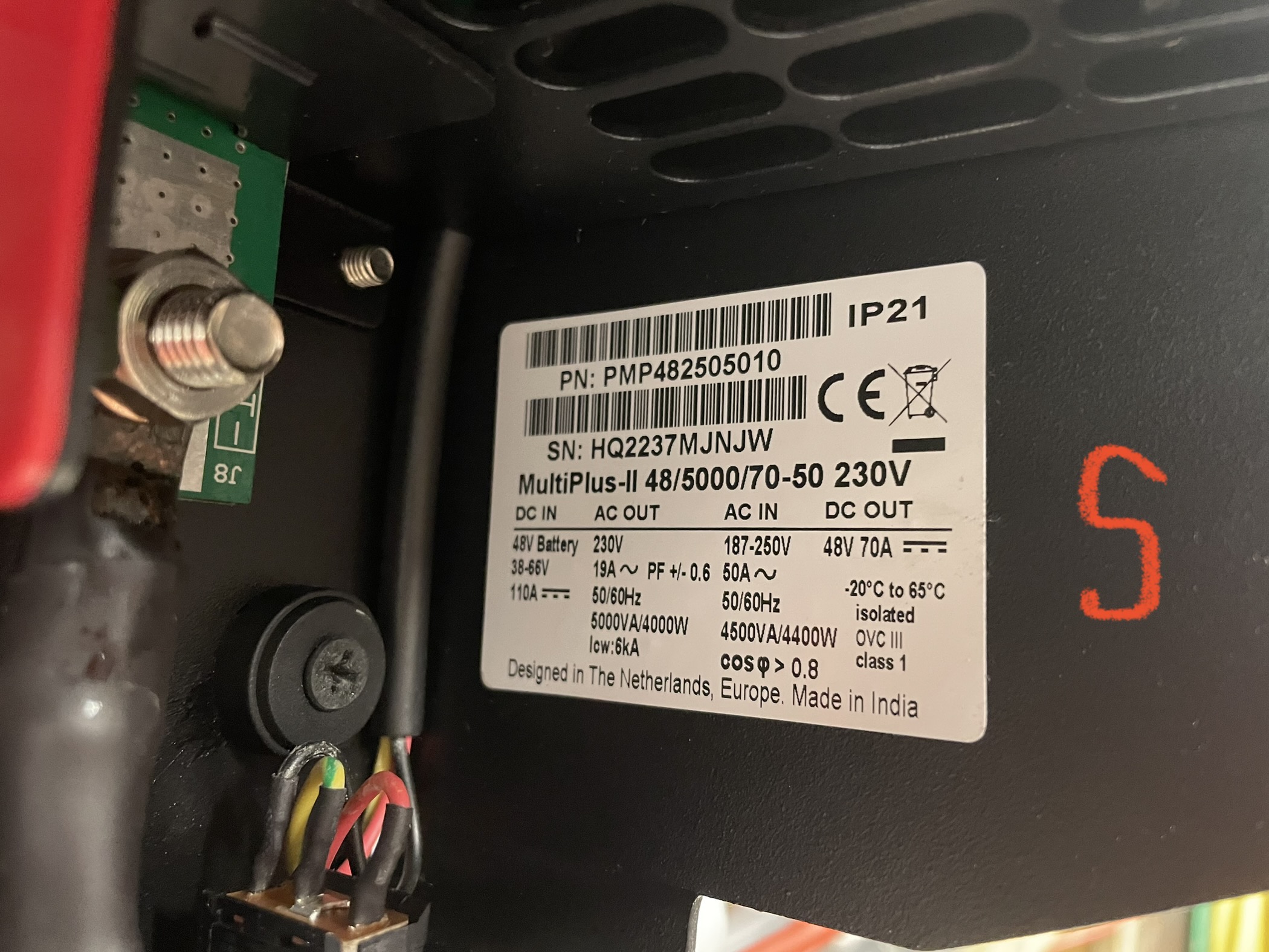
How close together are the manufacturing dates?
It all else fails best to get some proper support from your suppliers.
Hi Nick, I specifically ordered the second unit on the back of the first, about 4 week later. They said they would make them identical. Which they didnn’t. Never the less I upgraded the operating system to v.500 on both. Sadly proper support doesn’t exist.
ESS assistant must be loaded in all units in parallel.
 I’ve saved the ESS config file and loaded into the slave Multi. I’ve also wired both units in parallel including all of he AC in/out lines.
 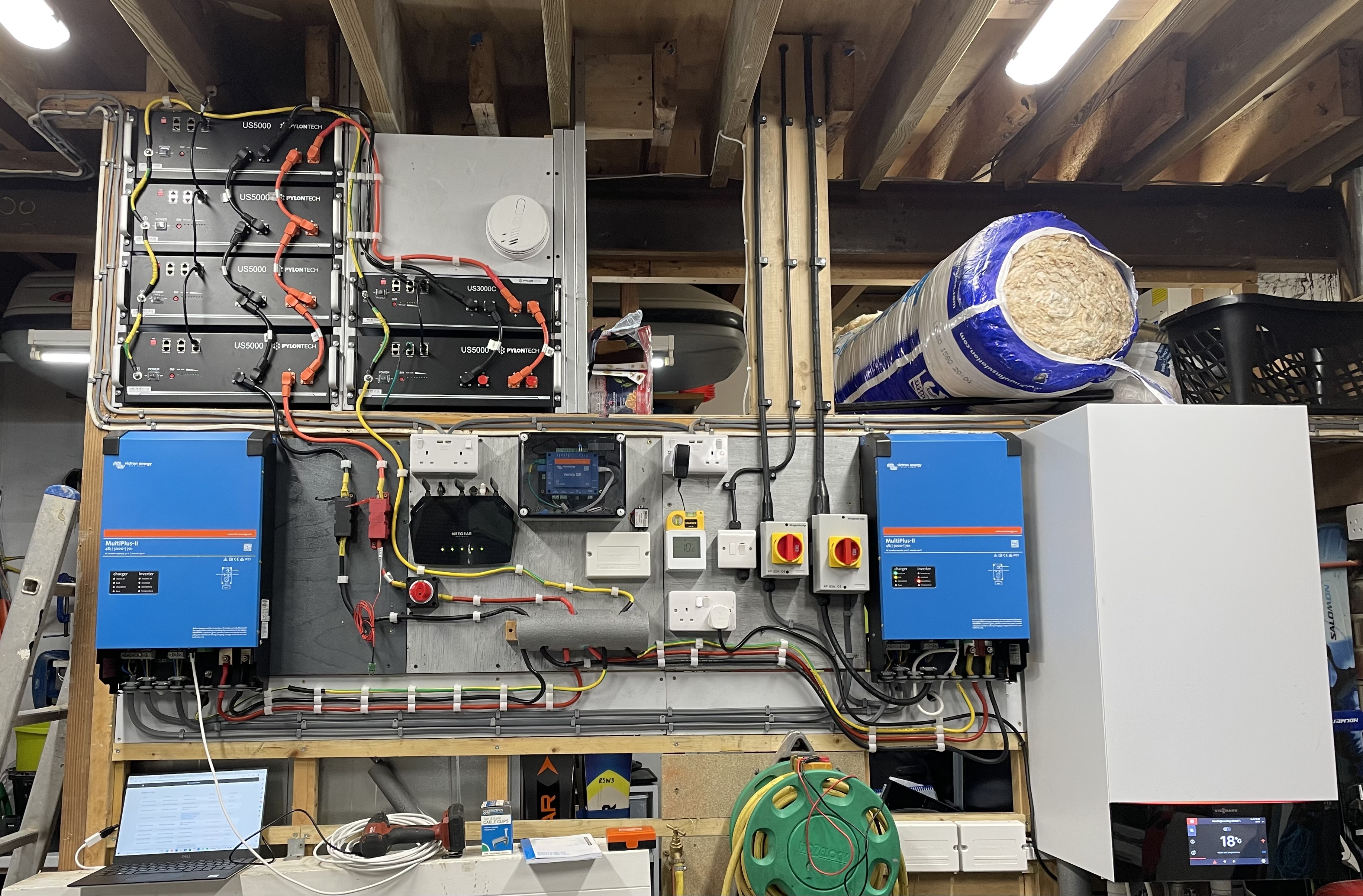 I’m still getting a low battery warning LED and output AC 1 is drawing from the grid rather than the batteries.
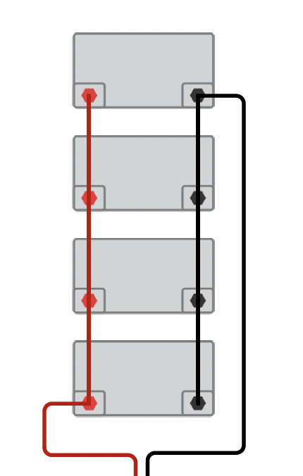
Looking at your battery parallel wiring, you might want to (re)read page 18-19 of Wiring Unlimited for a suggestion on how to take the leads off the battery bank to your installation to get better balance/duty cycles on your batteries by taking off the two ends of the string rather than from one battery.
Correct, my suggestion will not fix your immediate problem but will speak to the longevity of your batteries. Your datasheet indicates the batteries only support 121A-200A for 15 seconds. If you ran @ 130A for a while, I wonder if you did damage.
This limit is for one 5000 unit, but he has 5 of them in parallel.
The recommended current is 80A x 5 = 400A.
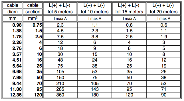
This much will not flow safely over 25mm2 because for this size the limit is 75A for 5m long wire.
This is beyond my personal practical experience, but I had assumed that with both leads from the bus to the bank wired to just the first battery, rather than 5x80A the first battery saw most of the load applied over the 30 minute sustained 140A charge vs the specified 121-200A 15 second peak limit. I could be wrong.
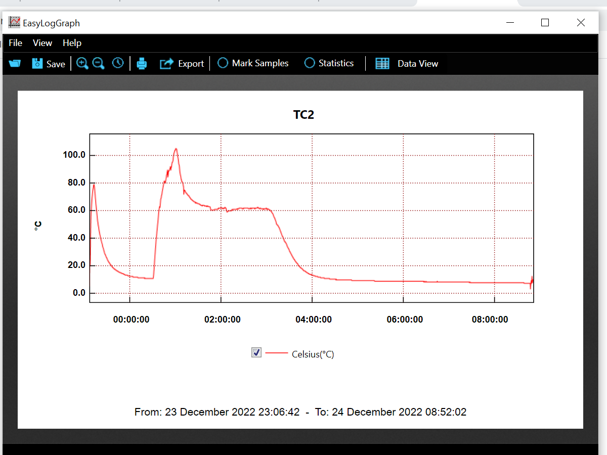 Yes that’s a good point. I would say I ran 138amps for 30mins and had a wide temp of 102°, I scaled this back to 100amps and the temp dropped to 60°. So yes I could have damaged the batteries. The recommended charge / discharge is 50amps but this must be per unit and when connected together in parallel this for 6 batteries comes to 300amps!
That set up worked fine for one Multi. I will change the length of the DC wiring from the RH multi.
1. It is safer to program master and slave separately. Saving setup from master and loading it to the slave not always is a proper way.
2. When your DC cables look close to be the same length (but I think they are not the same length), the AC cables are definitely not and this will cause an imbalance in power distribution between master and slave.
3. It is not low battery warning, it is alarm. Check if your Pylontech is not disconnecting from the system.
 I been through the videos (9.1 & 9.2) and passed the tests. I've altered the data cable to daisy chain them and disconnected the GX and then reinstalled the config set up by saving the file and loading it into the slave. Checked the connections on the batteries and changed the -ve DC cable to the end of the ring. Shut down the batteries and disconnected all cables and then restarted. Still getting an Alarm error code. In "On" mode getting 239v on AC 1 and then after a short pause 239v on AC 2.
From your battery datasheet, recommended amps is 80 with a max of 100A continuous. So I would dial your settings back. 25mm^2 wire size is small for 48V@130A over 2 meters - you should look at 35mm^2 or 40mm^2 if you want to have the option to sustain 100A.
He can run another set of standard PylonTech 25mm2 wires from the other end of the stack.
- Yes I was thinking of doing that, just want the system to work first!

Show us:
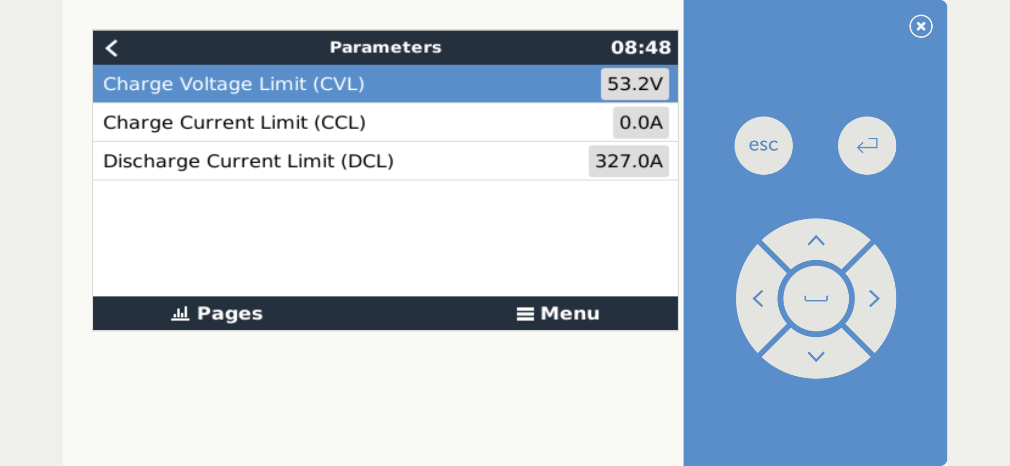
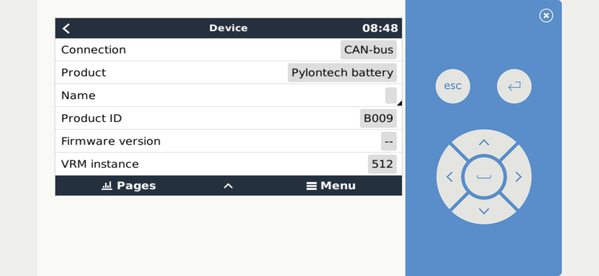
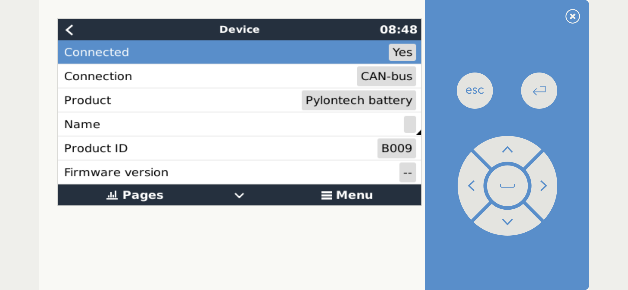
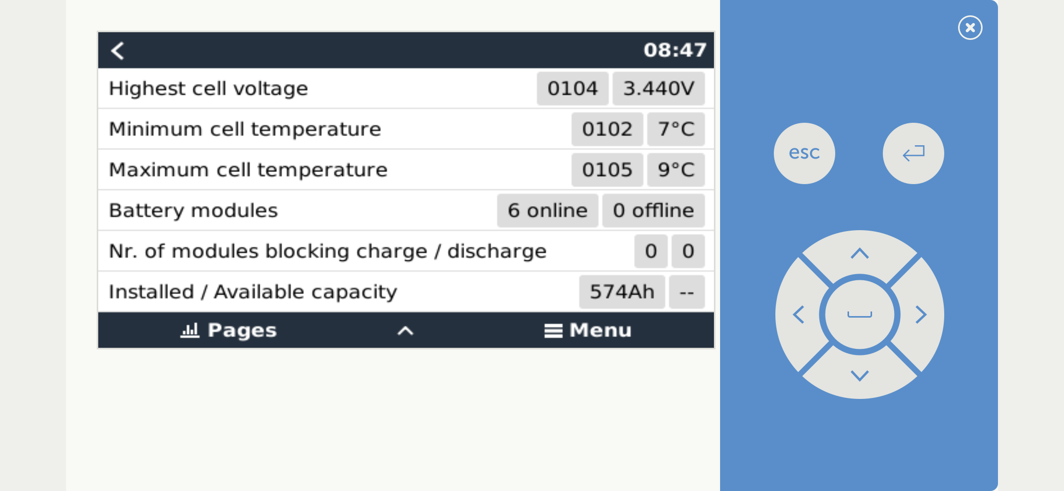
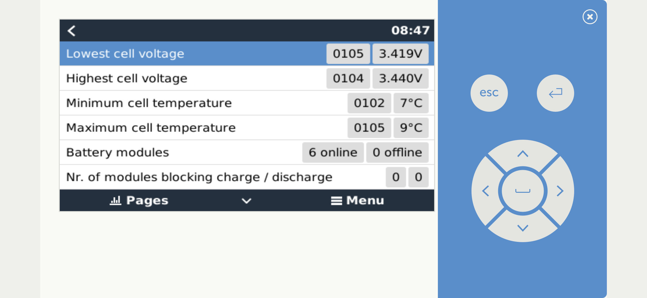
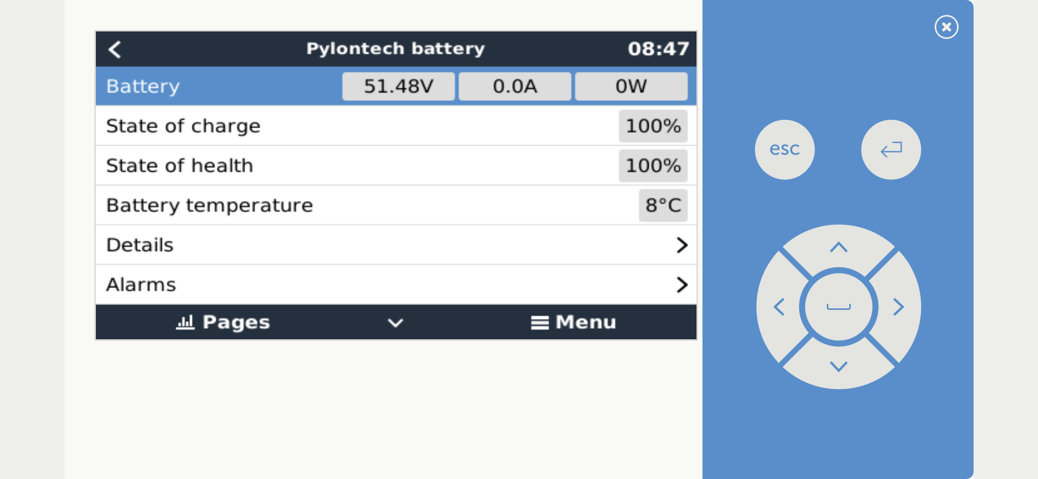
1. The PylonTech section in GX.
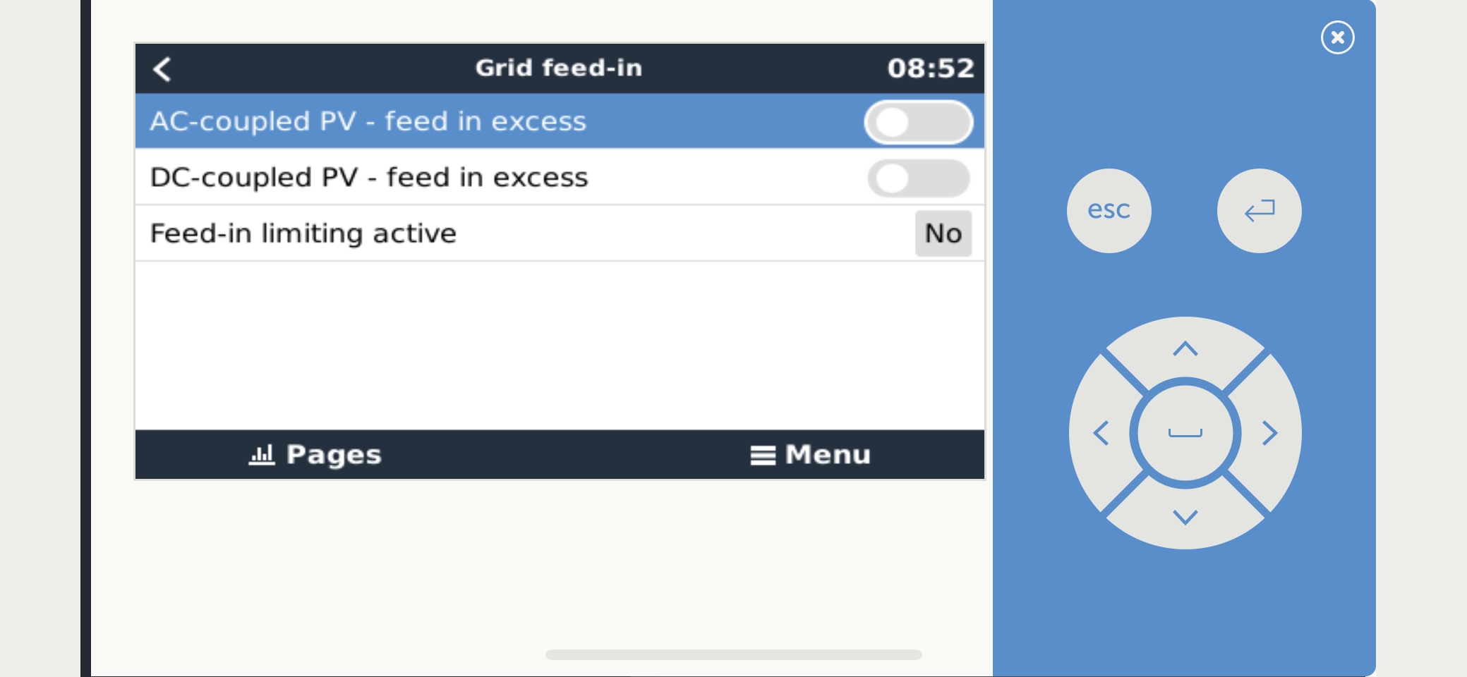
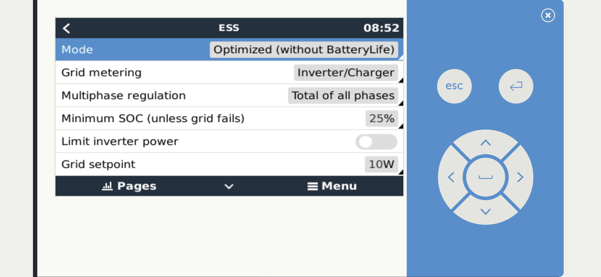
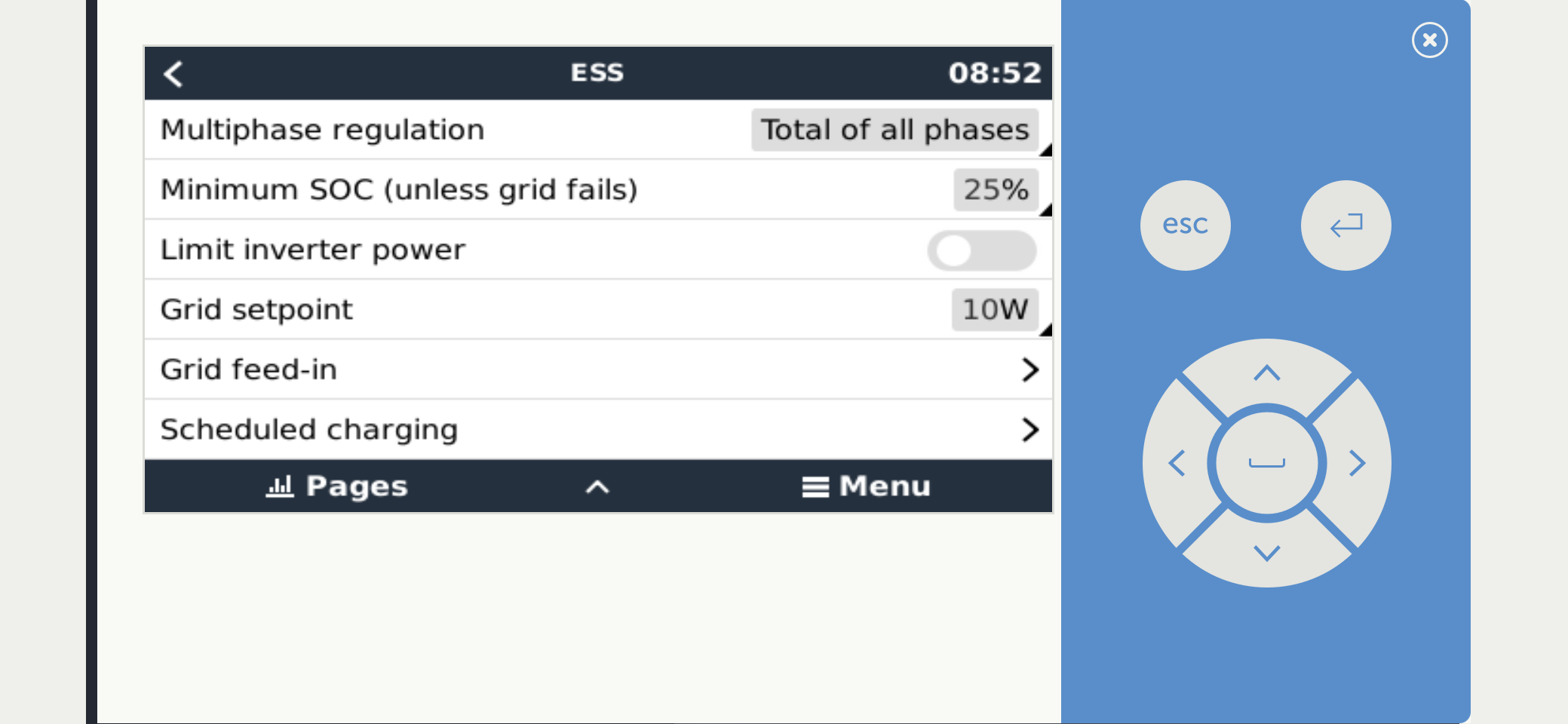
2. The ESS configuration and ESS section in GX
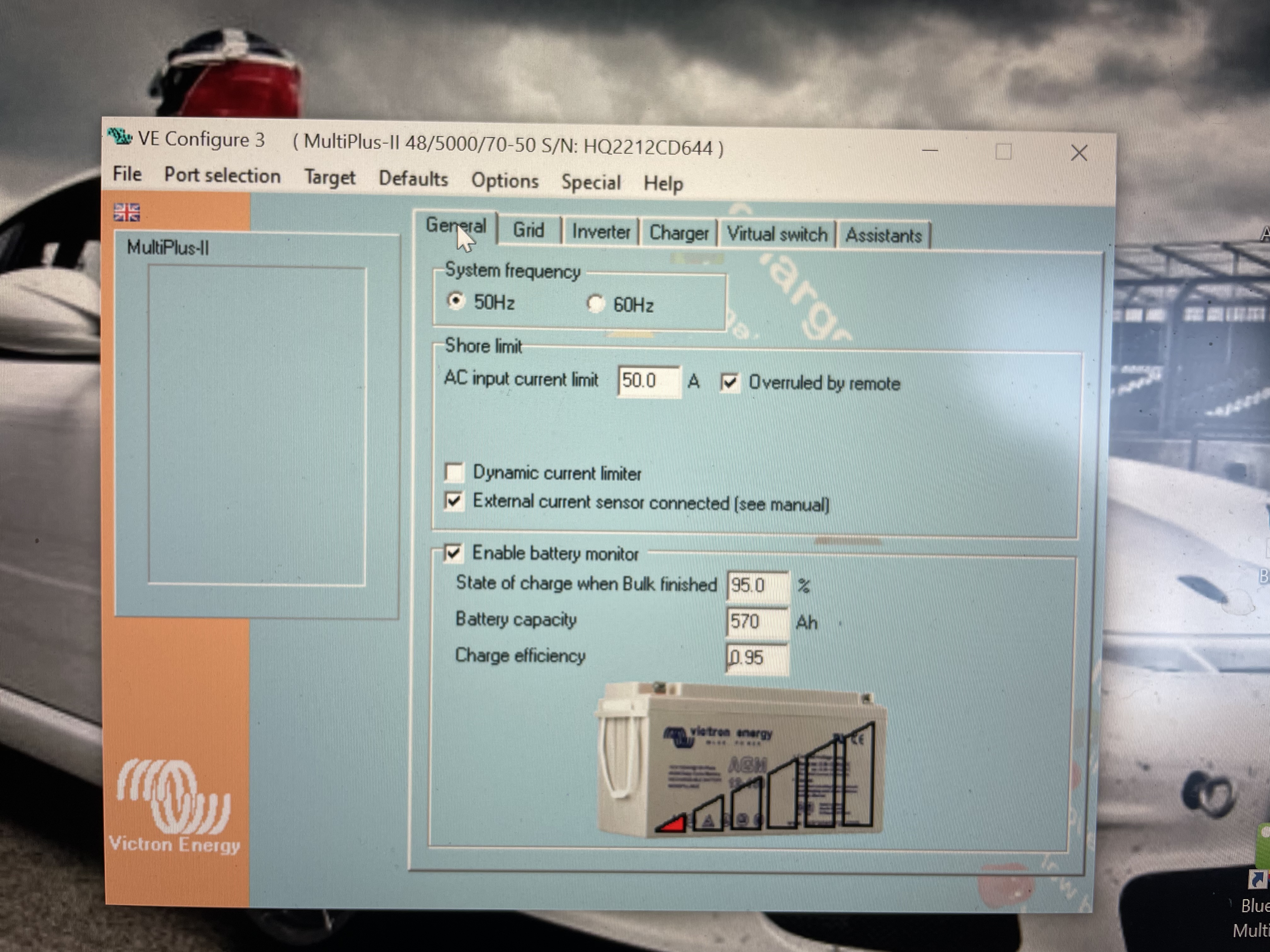
You should know that PylonTech battery is not 16s, like most other Lithium system, but 15s configuration.
Those numbers are not correct for PylonTech battery.

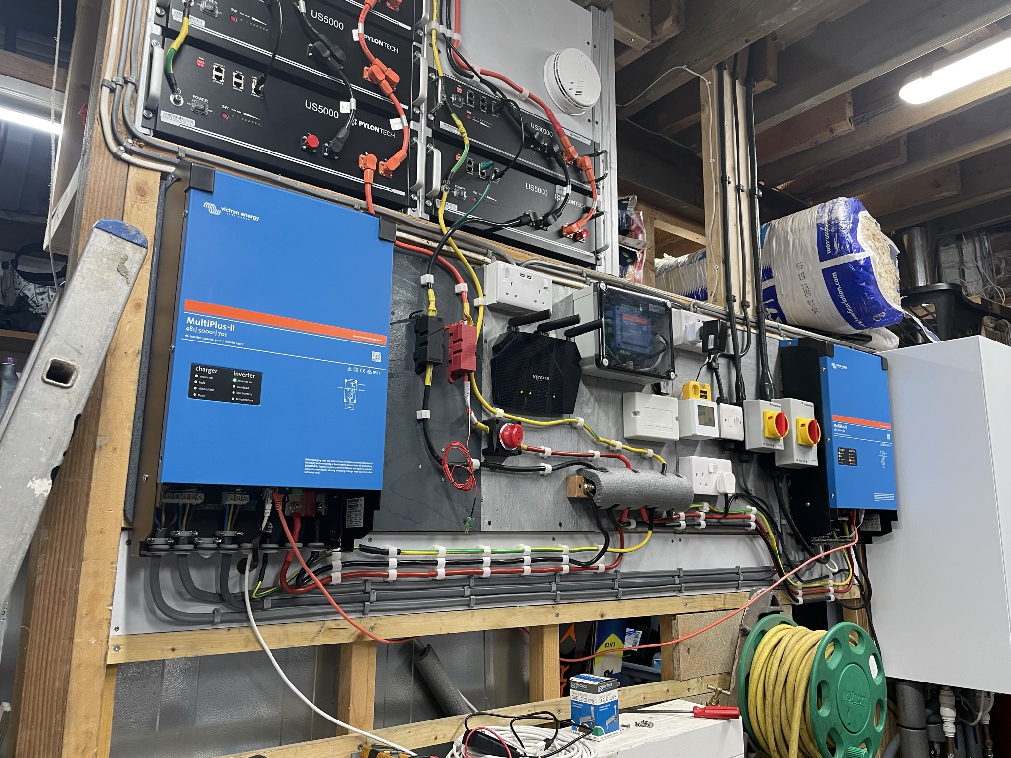
Do you have external current sensor connected?
I do not see it on you pictures.

You don't seem to have followed the setup instructions for pylon:
https://www.victronenergy.com/live/battery_compatibility:pylontech_phantom
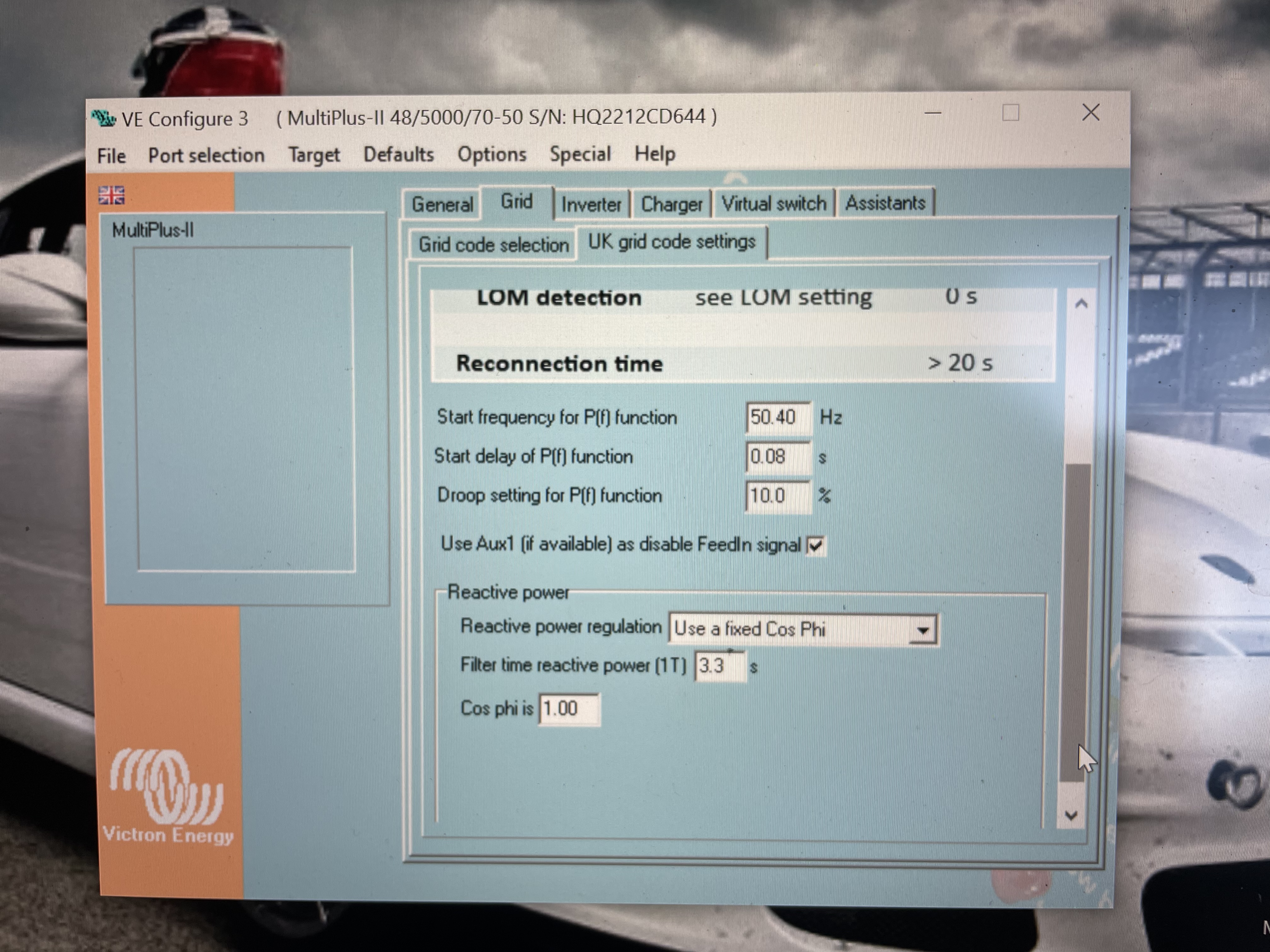
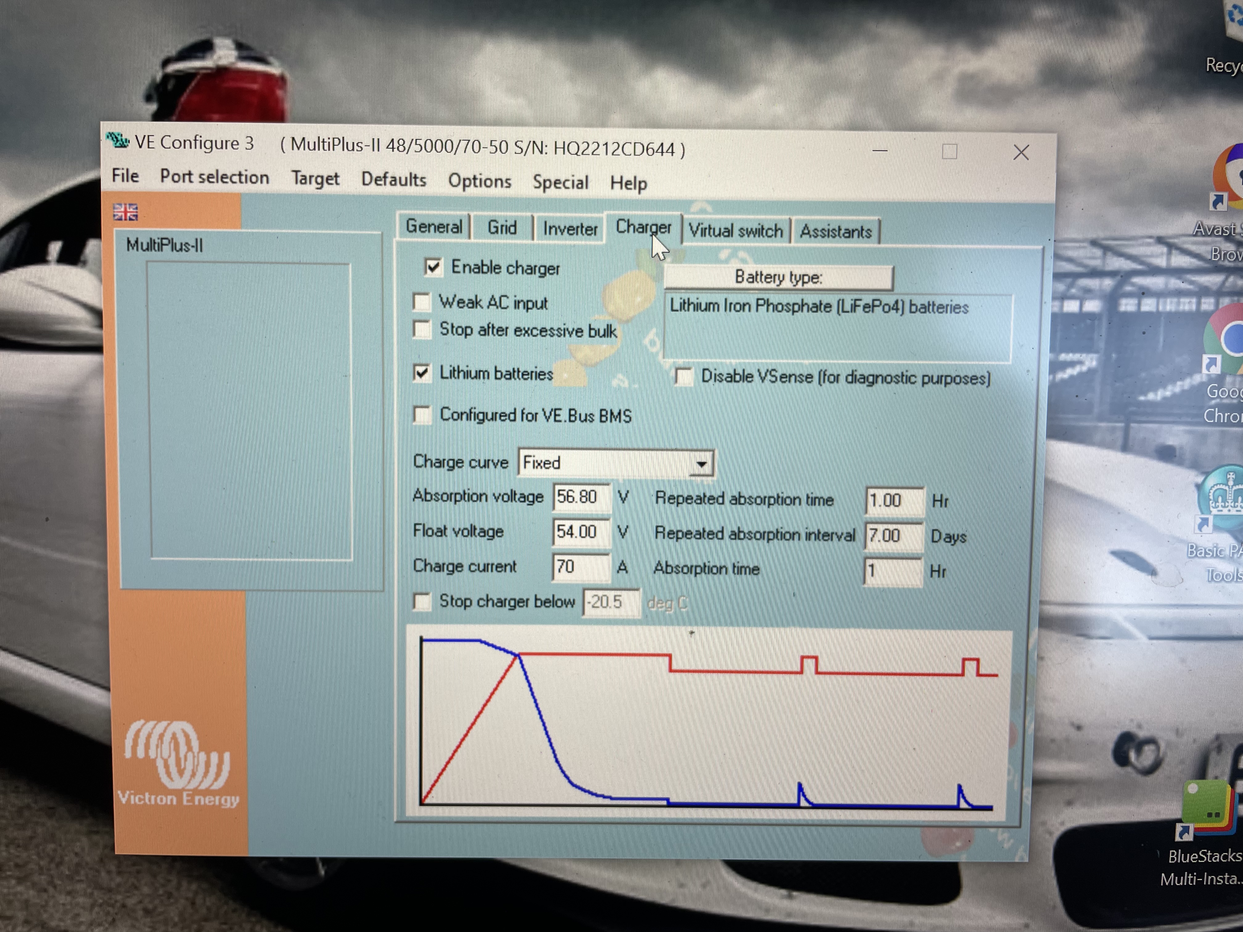
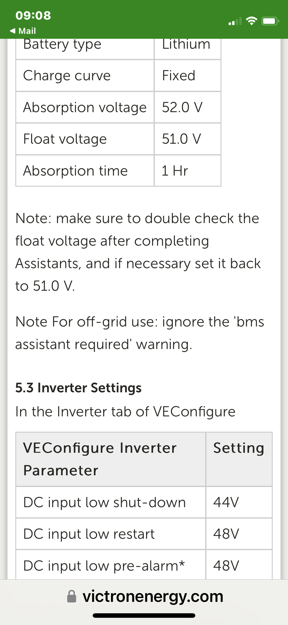
Your charge voltages are way too high, your restart values way too low etc.
You haven't shown the ESS parameters either for the assistant.
Everything needs to be followed word for word and you have not done so.
Please get someone who has done this before to assist you.
@nickdb
He had his PylonTech working for some time with the single MP setup.
It is strange that it is not working with two MPs in parallel, unless someone else did the single MP setup.
As you know, configs are wiped when changing to parallel. When none of the parameters match the setup required and this can't be found without going to the internet for help, then imo some onsite assistance is needed before something expensive breaks, or worse.
Internet communities are not well suited to triaging complex issues from a distance and with little to go on, it's the same reason why design discussions are discouraged here.
@nickdb
I know the setting are wiped but he had his system setup done once already, and if he did it himself, I would assume the second time will be done correct.
Maybe I am assuming too much.
If the voltages and settings in veconfigure are wrong, it is what it is.
It is also easy to download the config file from quick configure, zip it and post it here. Makes it simpler to check.
A couple of points. Your ESS assistant parameters are all off. They need to be configured exactly as per the pylon document linked to.
Configs must be identical on all units, as mentioned before, do not use the apply to all button, apply the config in turn from a corrected saved file.
Always use "apply all settings", not just the changes.
Your input current limit is 16A, that may be intentional (would give 32A max if both are configured the same).
Have you followed the US3000C/US5000 install guide to make sure the right battery is master?
Your inverter is also setup as 540AH capacity, should be 574 if irrc for that battery mix.
As already advised follow the recommended cabling from their install guide also.
Your ESS settings are wrong.
Follow the recommended settings step by step:
https://www.victronenergy.com/live/battery_compatibility:pylontech_phantom
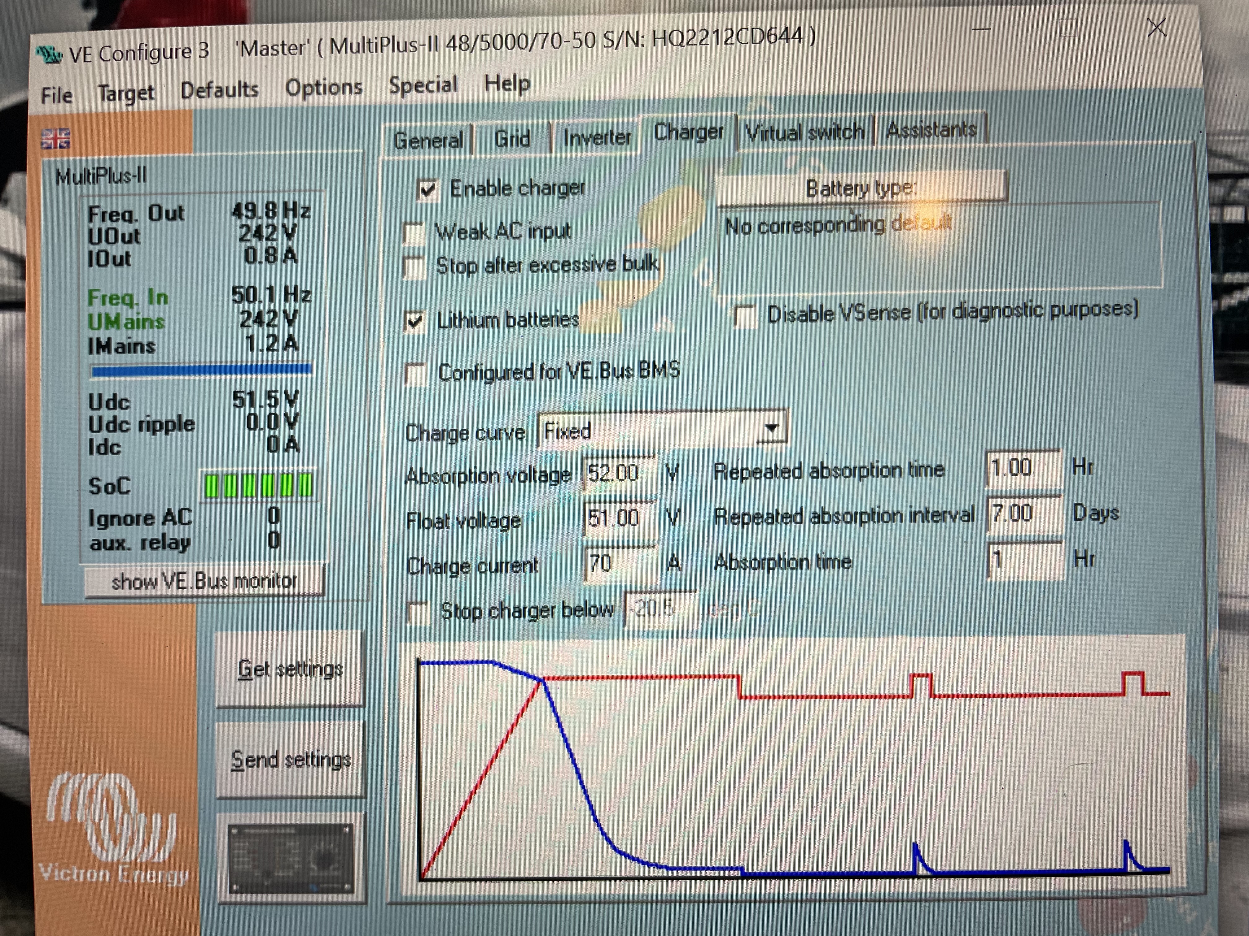 I see that when changing the Absorption and float voltages to 52 & 51 then battery type goes blank, presumably because these values don't correspond to a particular type of battery in the library?
 There was a couple of wrong values which I’ve changed:
The current situation (26/12/22) is that I’ve made a number of changes as detailed above. Then the ESS was not showing in the control panel and the Multis were in the software off mode even though they were (panel LED) on (master) and blinking (slave) but no way of switching them on. When going into the control panel there is “no ESS assistant found” showing, I’ve resent the VE Bus file to both. But still it doesn’t show.
I've updated the config files to bothe master and slave while disconnected to the gx device but it still doesnt shown on the control panel

If you can't see the multis on the GX you won't see ESS either. Make sure the mk3 isn't connected at the same time. Check all your VE bus cabling, if you have made your own, get ones that are known to be good.
Some times after changes the GX needs to be restarted to detect the assistant.
Failing that reflash them with VEFLASH and start with VE quick configure again, following Guy's setup video to the letter.
If properly wired and connected the setup is not complex, if the procedures are followed.
I did find that I had unplugged the GX!! So now it’s working. It’s actually discharging to the grid which I wasn’t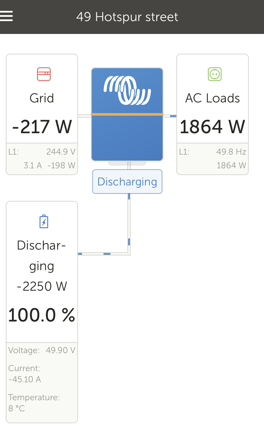 expecting! Will see how that goes.
Thanks all for your help. Sorry I’ve been a bit dim but it’s an area that needs to be learnt in order to get to net zero!
I connected a temperature sensor to the fuse M8 nut to see what temps I was getting on the DC cables. It’s wired back to the multi and so comes up on the VE as a battery temperature. It was working fine until it approached 60°c and then went to NaN, any thoughts? I switched in a new one and wired it to the other (master) multi but got the same response. Does that sensor have a range to only 60c?
@Richard Weir
If your cables are getting that hot (more than 60C) it means that they are waaaay to small for the current.
Since it was designed for battery temps and most batteries should not be operated over 60°C it would not need to read above that.
It is out of normal operation range.