question

allswell avatar image
allswell asked

24v Battery Bank in Float Before Bulk Charge Volts Reached

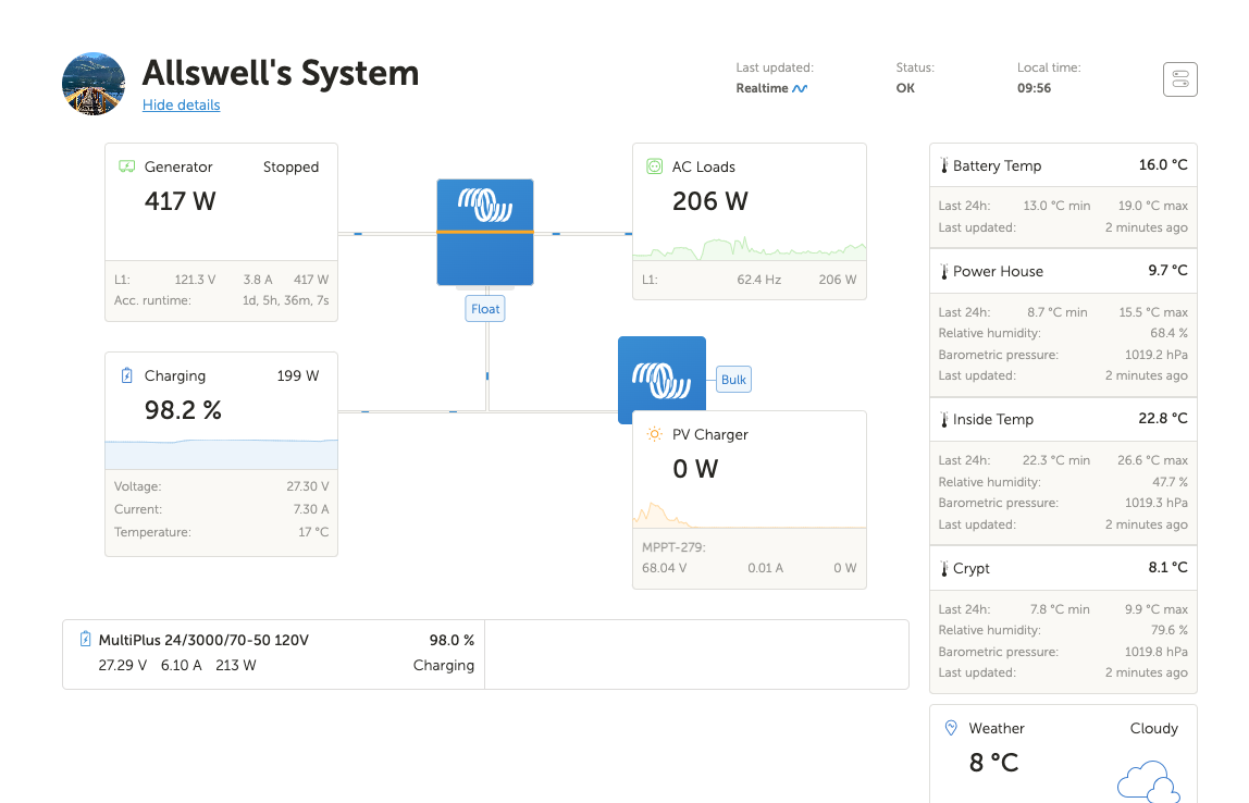
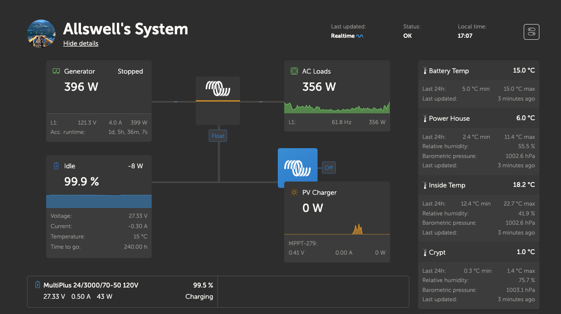
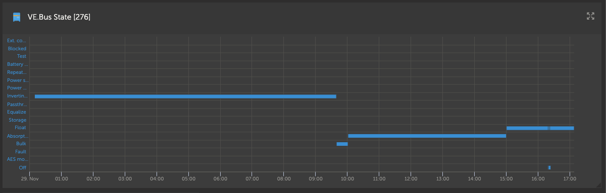
I have a 24v bank of fla's comprised of twelve 6v 235ah making a bank of 705ah. They are Rolls so I have set the charge voltage to 30 and float to 27 which is recommended. I've been charging this week to get a full deep charge accomplished in this new bank as it's been about a month now and we haven't done a full float on it. So, lots of charging. Right now though, the system shows that the volts is under the 30v that the charge is set to, but above the 27v that float charges at.

QUESTION: Did I wrongly assume that it would do a bulk/absorb charge to reach 30v, then switch to float to finish for an hour? Not sure why I'm seeing what I'm seeing. Is something wrong here or is something right here:

screen-shot-2022-11-25-at-95601-am.png

battery chargingfloat
5 comments
2 |3000

Up to 8 attachments (including images) can be used with a maximum of 190.8 MiB each and 286.6 MiB total.

ingo21 avatar image ingo21 commented ·

2.5 volt per cell is the max charge at @ 25°C (77°F) which is the 30 volts you set the charger.

i personally would not charge to the max charge voltage , depending on the battery temperature the battery might not like it and boil a lot of battery water like some other of famous brand does.

this might also be the cause of why the charger keeps charging a lot longer before it goes to float charge

maybe you could try to set the charge voltage to 2.45 which is the lower recommended setting. probably better for the battery life too.

0 Likes 0 ·
allswell avatar image allswell ingo21 commented ·

Thank you @Ingo21 for your contribution. I get what you're saying but I came across this Victron literature and then verified my batteries with the manufacturer:

"Some batteries however need a higher absorption voltage to fully charge them (tubular or thick plate deep cycle batteries for ex.), and open, flooded, batteries in general can be charged faster by not only increasing the bulk charge rate, but also the absorption voltage."

Rolls fla's are thick plate deep cycle which is why 30v is preferred.

0 Likes 0 ·
JohnC avatar image JohnC ♦ allswell commented ·

@Allswell

I suspect your batts are generic GC pattern floodeds. And you have 3x parallel strings of them. Not laboratory conditions, and a much stronger reason why you should be using 28.8V (or even less) as your base Abs V. The books never seem to mention string imbalance, which high charge V encourages. Nobody goes to bed thinking they'll have nightmares, but I'm sure that yours are coming early if you persist with 30V. (I use GC2's, one string of 48V, cos I've had my lot of parallel strings).

You won't notice the performance difference, if any.

In your screenshot above, your batts are in Float because they deserve to be, but we can't see the history. And I reckon your SOC should be closer to 99.0% actual. My genset would be stopped before the Multi got to Float, like ~96%. (yes, I see your 14.1A Tail, and that's ok, but my equiv @ 24V is 22A).

0 Likes 0 ·
allswell avatar image allswell JohnC ♦ commented ·

Thanks for your great advice @JohnC, much appreciated. So you're saying that thick plate deep cycle Rolls batteries are indeed generic GC pattern floodeds?

0 Likes 0 ·
JohnC avatar image JohnC ♦ allswell commented ·
@Allswell

I was surmising (a guess). GC's are endemic, and all Pb makers have em. Might even have 'GC' in their name. It means 'Golf Cart', and they're recognizable by 2 lifting tabs, squarish & slightly angled on their upside. Usually built rugged, with heavy plates and designed for deep discharge (as Pb's go). Think trips through the 'rough' and a fast recharge over lunchtime before another 18 holes in the arvo. Yet still good $ punch.

They've been around for yonks. Respond well to gentle treatment, and can last for many years, despite the lab boffins speccing stupid stuff for 'performance'.

Gentle does it..

1 Like 1 ·
4 Answers
bunya-solar-pl avatar image
bunya-solar-pl answered ·

"Right now though, the system shows that the volts is under the 30v that the charge is set to, but above the 27v that float charges at."

Could it be the temperature compensation of the charge voltage set points? Some of the temperatures displayed on your screen shot look coldish?

2 comments
2 |3000

Up to 8 attachments (including images) can be used with a maximum of 190.8 MiB each and 286.6 MiB total.

allswell avatar image allswell commented ·

Yes it could be? Just for clarity, the batteries reside in the power house which is semi-heated... so is typically around 10c. We have heating that kicks in when it gets to 5c to bring it back up to 15c so the battery bank won't freeze. The temp compensation is set to -48.00mV/°C honestly I do not know why. That's what my neighbour told me to do but he runs Trojan batteries, not Rolls.

In this article, Rolls suggests I do "Temperature Compensation: -5mv per Degree C for flooded models, multiplied by the number of cells. (+/- 120mv)" so should the setting in my MPPT say -60.00mV/°C instead of -48.00mV/°C?

See below.

Also, since we live at our off grid home full time, I would like to adjust the temperature compensation settings for the conditions of the day in which I am charging. When I look at this article, it is pretty clear that this is a good idea so that I can save fuel on charging ideally as a result. Can you help me how to translate a temperature adjustment for the temperature compensation so that I can do the math to figure out what -??.??mV/°C should actually be based on the ambient temperature of the day I am charging in?

I can do the math, I just need to understand the equation!

Thank you so so much!


screen-shot-2022-11-27-at-22153-pm.png


0 Likes 0 ·
allswell avatar image allswell allswell commented ·

As I struggle to understand how to set it on the fly, could you please confirm I have the math correctly?

My system is a 24v system so I have 12 cells. My charge voltage is 30V, and Rolls recommends a temperature compensation value of -5mV/°C/cell. When I started today's charge, my batteries were at 8°c.

So would it look like this:

-0.005V/°C/cell x 12 cells = -0.06V/°C.
The temperature compensation value is actually counting from 25°C, so 8°C-25°C = -17°C
-17°C x -0.06V/°C = 1.02V
1.02V + 30V = 31.02V.

So the battery charge voltage at 8°C would be 31.02v?

So if I was charging today and the batteries said they were 8c when I started, would I then set the charging voltage to 31.02v instead of 30v and then set the temp compensation to -60mV/°C/cell?


Please could you confirm?


0 Likes 0 ·
bunya-solar-pl avatar image
bunya-solar-pl answered ·

My understanding is that you set the temp compensation in the inverter / regulator and then the device does the maths and adjusts the charge set point according to the temperature info it receives from the temp probe. So you only need to enter the correct compensation once.

2 comments
2 |3000

Up to 8 attachments (including images) can be used with a maximum of 190.8 MiB each and 286.6 MiB total.

kevgermany avatar image kevgermany ♦♦ commented ·
Correct.


@Allswell Your -0.06V is all that needs to be entered in the Multiplus or Quattro. It's entered in mV, so -60 is what's needed.

Note that the system reports actual values, so the only mental gymnastics required is to accept that the system is doing its job. If you wish, you could draw up a table of float and absorption voltages at relevant temperatures.

Back to your original question, system will charge up to the set absorption voltage, then hold that until either charge current drops to tail current setting, or absorption time exceeded. Then drops to float. It will generally stay in float until you apply a significant load. Note my vagueness, it's intentional. Don't worry about long periods of float even if you have loads switched on. Unless battery voltage drops much below compensated float voltage.


0 Likes 0 ·
allswell avatar image allswell kevgermany ♦♦ commented ·
Thank you so much everyone, great information and wonderful support. So much appreciated.
0 Likes 0 ·
allswell avatar image
allswell answered ·

In this article by Rolls, they specify for Rolls fla's:

Programming with an adequately sized PV array with an average peak output of 100 Amps:

Bulk/Absorption voltage: 2.45 to 2.5vpc (58.8 to 60-volts)
Absorption Time: .42 X 890 AH / 100 Amps = 3.74 hours
Float Voltage: 2.25vpc (54 Volts)
Float Time: 1 hour
Equalization Voltage: 2.6VPC (62.4 Volts)
Equalization Time: generally 3-4 hours or 50-75% of the Absorption charge time.
End Amps: 2% of the C/20 or 20 Hr AH rating of the battery bank for 60 minutes (18 Amps)
Battery Efficiency Percentage: 80% for flooded lead-acid models
Temperature Compensation: -5mv per Degree C for flooded models, multiplied by the number of cells. (+/- 120mv)

The sample above is for a 48v system. With mine being a 24v system it would look like this but I have some blanks:

Programming with an adequately sized PV array with an average peak output of ??? Amps:

Bulk/Absorption voltage: 2.45 to 2.5vpc (29.4 to 30-volts)
Absorption Time: .42 X 705 AH / ??? Amps = ??? hours
Float Voltage: 2.25vpc (27 Volts)
Float Time: 1 hour
Equalization Voltage: 2.6VPC (31.2 Volts)
Equalization Time: generally 3-4 hours or 50-75% of the Absorption charge time.
End Amps: 2% of the C/20 or 20 Hr AH rating of the battery bank for 60 minutes (14.1 Amps)
Battery Efficiency Percentage: 80% for flooded lead-acid models
Temperature Compensation: -5mv per Degree C for flooded models, multiplied by the number of cells. (+/- 120mv) My setting is -60.


My question is how can I figure out the average peak output of my pv in amps? That really seems to be hanging me up here in terms of settings at this point which I suspect is creating some of the issues I'm having?


6 comments
2 |3000

Up to 8 attachments (including images) can be used with a maximum of 190.8 MiB each and 286.6 MiB total.

JohnC avatar image JohnC ♦ commented ·

@Allswell

Try not to overthink this. A fair design point is like 10% solar A of your 705Ah. So 70A, or ~1700W. Nice if this can be achieved before midday, but whether it's enough overall also depends on how much you're drawing down your batts overnight. And of course your weather.

I wouldn't equalize the batts, and I use 3% (shunt/mppt) End Amps to terminate Abs. That leaves like <1% SOC to smooth off in Float, easy. 1 to 1.5 hr Abs usually enough.

1 Like 1 ·
allswell avatar image allswell JohnC ♦ commented ·

Okay, I think I'm almost at the end of this settings learning curve. With everyone's generous support, I'm going with an amperage of 50a for the PV array which is the calc for the area average, though we are getting barely any solar at this time. So, I'm inputting these settings:

PV array with an average peak output of 50 Amps:

Bulk/Absorption voltage @ 2.45 to 2.5vpc: My Setting is 29.4
Absorption Time: .42 X 705 AH / 50 Amps = My Setting is 6 hours
Float Voltage @ 2.25vpc: My Setting is 27 Volts
Float Time: 1 hour
*Equalization Voltage: @ 2.6VPC: My Setting is 31.2v *See below
Equalization Time: My Setting 4 hours which is 75% of absorption time
End Amps @ 2% of the C/20 or 20 Hr AH rating of the battery bank for 60 minutes My Setting is 14.1 Amps
Battery Efficiency Percentage: My Setting is 80% for flooded lead-acid models
Temperature Compensation: -5mv per Degree C for flooded models, multiplied by the number of cells. (+/- 120mv) My setting is -60.

Here's what's happening with the system when I charge with these settings:

The system goes through absorption at 29.4+ volts and does that for it's time, then drops into float at 27v. I ensure that it has at least it's 1 hour in float and then I turn the genset off (if there is no solar that day).

When I'm turning the system off however, it stays at the 27v from float... and starts to discharge from there. So the gain in volts in the absorption phase just seem to have gone, POOF! so my 100% isn't really 100%, it's 27v not 29.4v so I'm always starting the discharge lower than what the absorption seems to have put the batteries at.

Is that normal?

I assumed with the charge phases complete that I would have a fully charged battery at the top of it's voltage and amps, ready to discharge from a true (or as true as I can get it) 100%.

Was I wrong?

0 Likes 0 ·
allswell avatar image allswell allswell commented ·

Here's where it got to on my last charge, you can see it's almost there, the float is almost complete and we are almost at 100%...screen-shot-2022-11-29-at-50746-pm.png

I ran the float for at least the hour...screen-shot-2022-11-29-at-50914-pm.png

And only ended up with a 27v bank to start discharging... there was also voltage drop as soon as I turned off the genset so it actually started to discharge about 26v or so...

?

0 Likes 0 ·
kevgermany avatar image kevgermany ♦♦ commented ·
Take the array size in Watts, look up one of the web sites that gives average/peak yield for your area. Calculate charge current as yield/charge voltage.
0 Likes 0 ·
allswell avatar image allswell kevgermany ♦♦ commented ·

Thank you @kevgermany, much appreciated. My panels are LS60-375M-B LONGI 375W Mono Black/Black/White 35MM Frame Solar Panel and I have four of them. So that's 1500w. This website states that annual pv production for my area is 1004kwh per year but isn't that dependant on how many panels one has, how big they are? I'm confused as to how to calculate charge current as yield divided by charge current though?

Could you please share more details about how to find this information?

0 Likes 0 ·
kevgermany avatar image kevgermany ♦♦ allswell commented ·
It's in kilowatt hour per kilowatt per year. So if they say 1500, you'll get 1500 kilowat hours for every kilowatt of panels, per year.


But I think @JohnC is better placed to help here.

.


1 Like 1 ·
allswell avatar image
allswell answered ·

Thank you so much @JohnC and @kevgermany for your contributions. You are helping the community so much, and me.

: )

2 |3000

Up to 8 attachments (including images) can be used with a maximum of 190.8 MiB each and 286.6 MiB total.

Related Resources

Additional resources still need to be added for this topic

VictronConnect VE.Bus charging manual