question

thanar avatar image
thanar asked

Limit battery usage with no GX device

I will be installing a new system, but the proper battery install will delay for a bit. Same for the Cerbo installation.

So, the system will get online using a 48V LFP battery with no communication, that has a limit of 100A constant discharge current, charging from solar. Math works out, but I also want to limit battery usage (system will be connected to the grid as well).

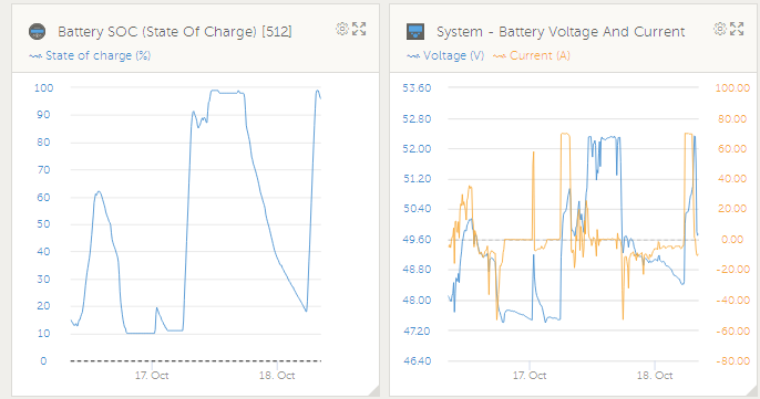
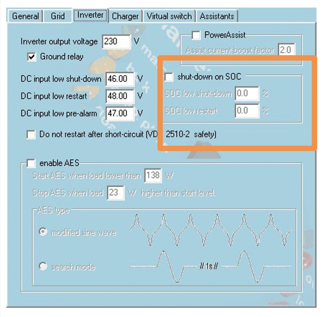
Is there a way to limit battery usage in this case? If I went li-ion, I would have been able to set low voltage limit on the Multiplus and it would stop inverting at that point; however, the LFPs have a very flat voltage curve, and I don’t think this trick will work, as it does on another installation of mine.

In other words, I want full inverter power when solar is available, but when there is not enough solar, I’m trying to find a way to limit battery discharge percentage. No GX communication at the moment.

Any ideas?

Multiplus-IILithium Batteryfeed-in limit
4 comments
2 |3000

Up to 8 attachments (including images) can be used with a maximum of 190.8 MiB each and 286.6 MiB total.

thanar avatar image thanar commented ·

Hello,

The system has been set up and we are trying to decide on the proper parameters. However, on first glance, it seems that it does not work exactly as expected.

Basic issue seems to be that when AC power is available at the AC-in of the Multiplus-II, the inverter switches to "passthrough" mode, and it is not using any power from the DC BUS. Is there a very basic setting I'm missing? I was expecting that it would be "assisting" the grid, since I want to use the available solar power first and only revert to the grid when the DC-in voltage would drop below a certain threshold.

What am I missing?

@sharpener @Alexandra

0 Likes 0 ·
Alexandra avatar image Alexandra ♦ thanar commented ·
@thanar A GX device

You are asking for an AC ignore system or self consumption system.

Try looking at the conditional ac comnect settings in victron connect with the mk3. It will allow you to connect above a certain load. Disconnect over a certain SOC. And a few others.

Or the virtual switch settings if using ve config (basically the same thing)

The other way is to treat the grid like a generator.


0 Likes 0 ·
thanar avatar image thanar Alexandra ♦ commented ·

Please have a look at the following fresh thread, I think I make the goal of the system more clear:

https://community.victronenergy.com/questions/179316/ess-less-multiplus-ii-with-support-from-the-grid.html

0 Likes 0 ·
thanar avatar image thanar commented ·

System has been set up, but I've run onto a bunch of issues. At the moment, I am still waiting for the Cerbo GX, to be able to set it up properly as an ESS system, so the system is working as a stand alone solar setup that is switching to the grid, by utilizing the "AC input control" settings.

However, it seems like 5kWh is kind of out of specs for this system, or the battery I am using is of a very low quality: As soon as the inverter tries to draw over 2000W and there is no solar coming in at that moment to compensate, I am getting DC ripple warnings and occasional faults. Obviously, getting too high of a voltage sag for some reason. The inverter doesn't even have the chance to which to the grid.

I am keeping the low voltage "switch to the grid" very high at the moment at 51V (battery is being charged up to 54V), because while I was fiddling with the settings and trying lower battery disconnect voltages, I had an overshoot out of the Multiplus that roasted a 365V varistor out of a garage door opener!

Hoping I will be able to better balance the system when enabling ESS.

0 Likes 0 ·
3 Answers
sharpener avatar image
sharpener answered ·

Actually the SoC and terminal voltage are pretty well correlated, except there is about 2.0 volts of hysteresis between charging and discharging

1666078460620.png

N.b. these screenshots are for a Pylontec battery with only 15 cells.

So in my case setting a cutoff at 48.0V would work as you suggest to keep the battery from being completely discharged.

(In fact I have implemented a stepwise discharge current limit between 48.0 and 47.0 using NodeRed to act before the BMS cuts the system off entirely.)


1666078460620.png (37.1 KiB)
3 comments
2 |3000

Up to 8 attachments (including images) can be used with a maximum of 190.8 MiB each and 286.6 MiB total.

thanar avatar image thanar commented ·

Thanx a bunch for the comment. I didn't know that LFPs have such a discreet hysteresis. So I guess this specific trick will work just fine, until I manage to expand the system at its proper magnitude.

If I may ask for a bit more information:

  1. Where's the output graphs from? Is your 15 cell Pylontech battery connected through CANbus to a GX device? Or are you using a Victron Shunt to determine the real SoC?
  2. What is NodeRed?

Thanx again.

0 Likes 0 ·
sharpener avatar image sharpener thanar commented ·

1. Pictures are from Multiplus II-GX 5kVA connected to the BMS which provides the battery data, AFAIK it gets the SoC from the BMS

2. Programming tool, you will need to load the Large version of the Venus OS, see Modifications section of this forum

3. I am not entirely sure where the inverter gets the SoC information for the inverter settings tab if there is no connection to the battery, @Alexandra may know. But it should work OK by setting voltage limits on their own.

Provided you have a functioning BMS it should effectively protect the battery under any circumstances, they are designed to do their job even if the inverter connection is down. Have you tried it in practice?


1 Like 1 ·
Alexandra avatar image Alexandra ♦ sharpener commented ·
@sharpener

@thanar

The multiplus works out the SOC internally. Have found it fairly accurate. Have set it even for the bms controlled systems

0 Likes 0 ·
Alexandra avatar image
Alexandra answered ·

@thanar

On the inverter tab in victron connect you set the low cut off and can have the system shutdown on a specific soc.

To limit yourself on discharge by not having big loads.

4 comments
2 |3000

Up to 8 attachments (including images) can be used with a maximum of 190.8 MiB each and 286.6 MiB total.

thanar avatar image thanar commented ·
Indeed, but I am worried that the LFPs will not have a discreet enough voltage difference for most of their discharge curve, since their curve is not linear, but only drops really fast close to 15% SoC.
0 Likes 0 ·
Alexandra avatar image Alexandra ♦ thanar commented ·

...

screenshot-20221018-131024.jpg

0 Likes 0 ·
pwfarnell avatar image pwfarnell commented ·
The original post states that there will be solar charging, tje inverter does not measure the solar charge current, it knows nothing about this without a shunt and Cerbo or comms from the BMS. The inverter SOC will not be reliable until comms are added to the system.
0 Likes 0 ·
Alexandra avatar image Alexandra ♦ pwfarnell commented ·

Going to assume here that low soc is not going to be a problem when there is enough solar. So two conditions set with voltage and soc it will be fine.


I have two systems that run with no bmv using only ve bus soc and have had no issues to-date. (And one was checked with a bmv that had no comms with the system to be sure). One offgrid, one on.

As long as there is no run of bad weather for a few days and the vebus soc gets to 100% through the whole bulk absorption float stages, without issues the low soc cut off will be fine to use

0 Likes 0 ·
sharpener avatar image
sharpener answered ·

OP says <48V LFP battery with no communication> so the inverter will not get SoC from the BMS.

However IME the terminal voltage is only steady down to about 70% SoC, below that it falls steadily as shown above, so you should be OK setting a minimum voltage limit

2 |3000

Up to 8 attachments (including images) can be used with a maximum of 190.8 MiB each and 286.6 MiB total.

Related Resources

MultiPlus-II Product page 

MultiPlus-II Manual

MultiPlus-II 230V Datasheet 

VE.Bus Error codes

Additional resources still need to be added for this topic

Battery Compatibility

Did You Know - How to create a battery profile for non-Victron batteries?

Additional resources still need to be added for this topic