question

Thierry Douet avatar image
Thierry Douet asked

Charger and SmartShunt and Inverter current going the wrong way and miss representing SOC

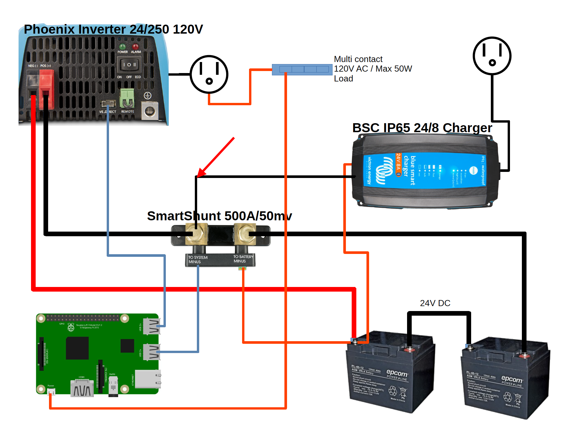
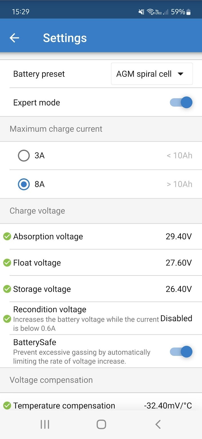
I have a need to keep 120V maximum 50W of load powered in the case of a power outage and to be able to remotely monitor the SOC of the batteries. The configuration runs off of 2 x AGM 12V 100Ah batteries connected in series with a SmartShunt 500A, a Phoenix Inverter 24V 250VA 120V, a Blue Smart IP65 24V 8A charger all connected to a Raspberry Pi acting as a CerboGX.

screen-shot-2022-09-26-at-102821-pm.png

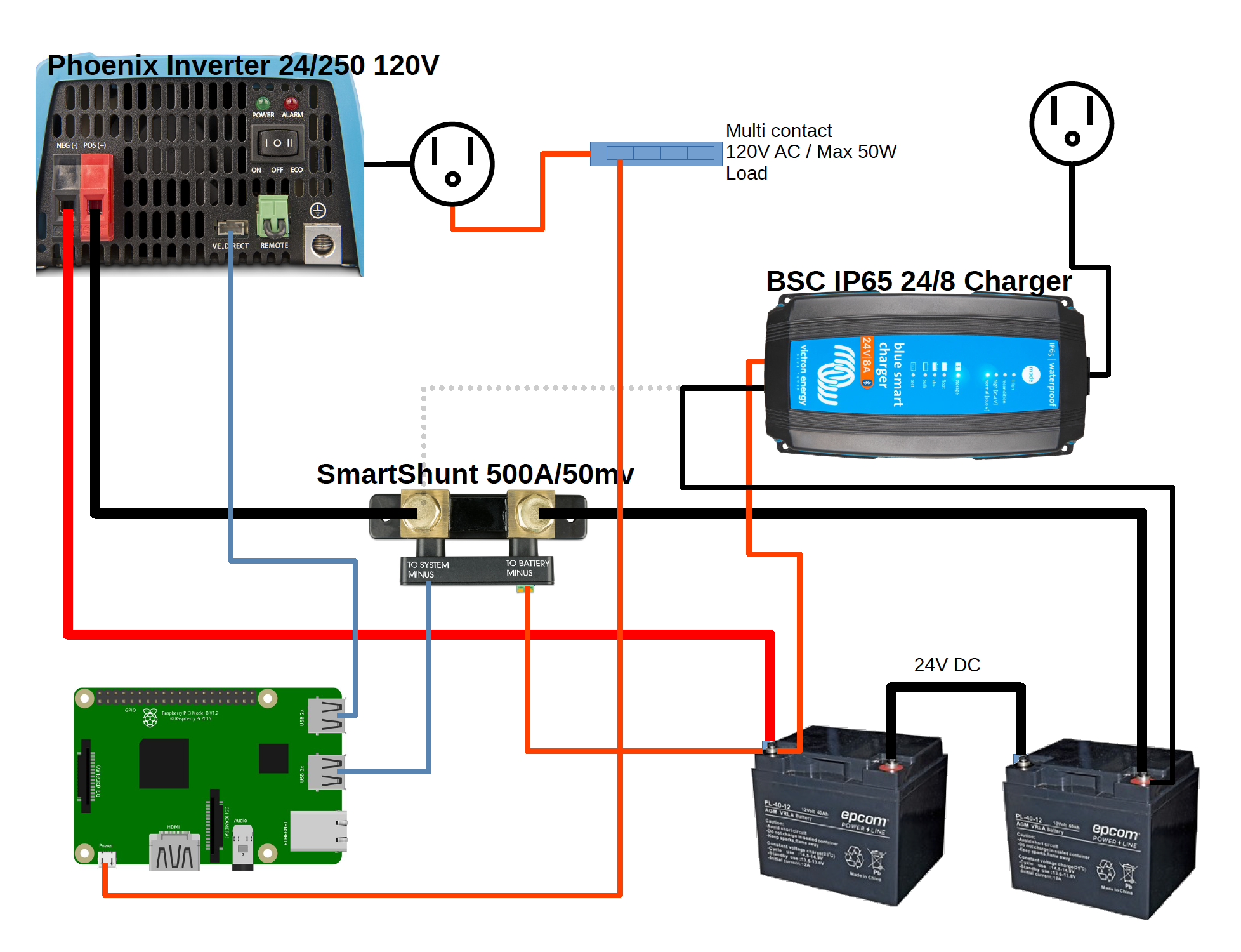
Both the SmartShunt and the Inverter are connected to the Pi via the VE.direct to USB cable and are visible via the VictronConnect Application and VRM.

Since the Charger only has Bluetooth capability, we can not manage it remotely, but only locally which is fine. But non of the devices talk to each other over a virtual Victron wireless network like a SmartShunt can with an MPPT for example.

soc-and-current-flow-vrm.png

The problems that I am seeing are the following:

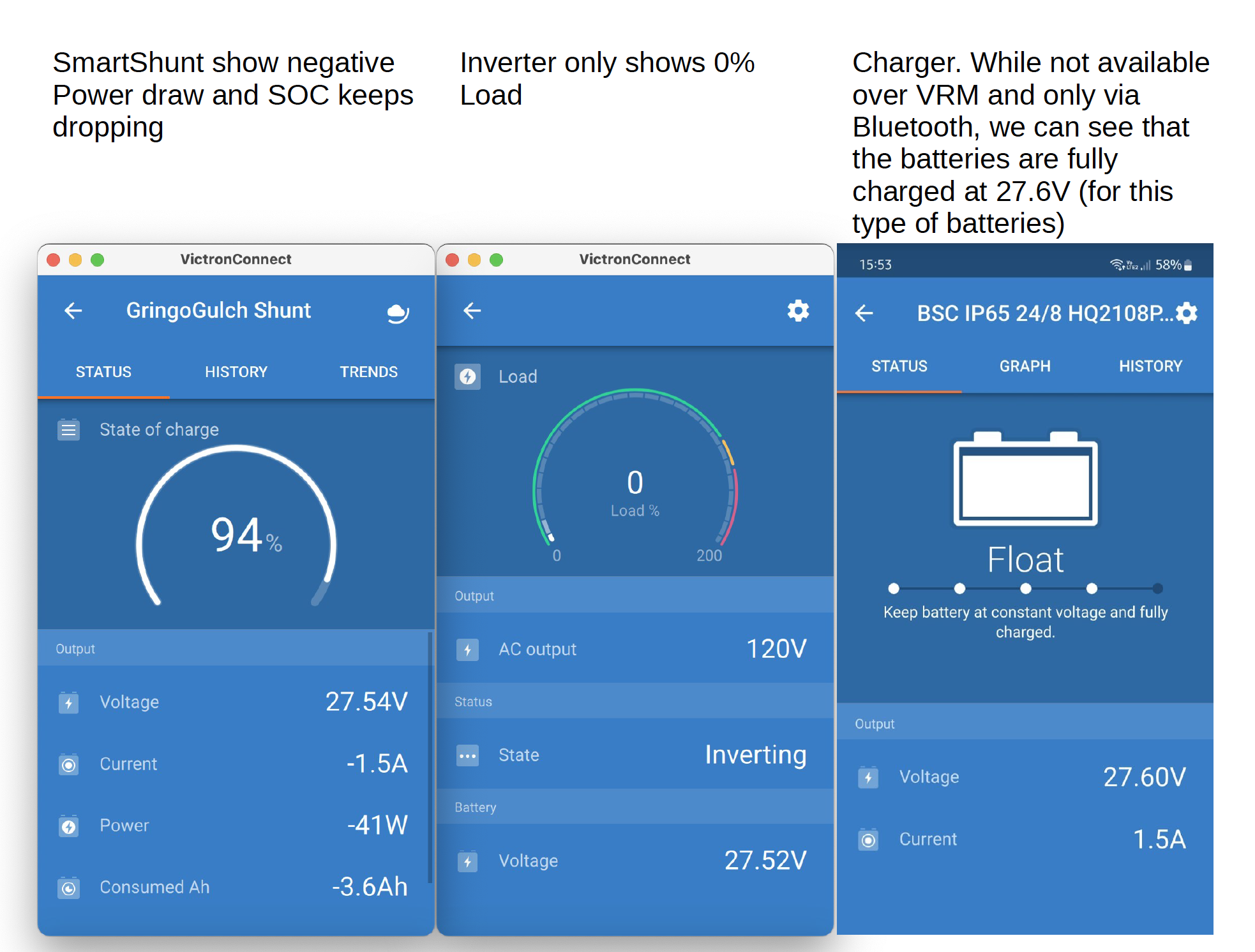
  1. When looking at the inverter, it only show 0% load. That value never changes.
  2. When looking at the SOC on the SmartShunt for the batteries, they are continuously reporting as discharging even though the Charger is permanently connected and charging the batteries.
  3. In the VRM portal, the current flow is going from the batteries to the Inverter and not from the Inverter to the batteries as I would have expected it since the inverter is supposed to keep the batteries topped off when AC power is usually available.

Is this configuration simply not possible because each element do not have a way of communicating to each other?

Or is the Charger not to be connected to the negative terminal of the battery bank but needs to go through the system Negative of the SmartShunt? (I have tried that but to no difference).

victronconnect-screenshots.png

The setup is available at https://vrm.victronenergy.com/installation/216745/share/97d4ba88

Thank you for any help anyone can provide.

battery chargingVRMchargerSmartShuntPhoenix Inverter
2 |3000

Up to 8 attachments (including images) can be used with a maximum of 190.8 MiB each and 286.6 MiB total.

9 Answers
Matthias Lange - DE avatar image
Matthias Lange - DE answered ·

As always take another look into the manual.

Only the battery should be connected to the "to battery minus" side of the shunt everything else to the "to system minus" side.

How should the shunt measure and show the charging current if you bypass the shunt?

1 comment
2 |3000

Up to 8 attachments (including images) can be used with a maximum of 190.8 MiB each and 286.6 MiB total.

pwfarnell avatar image pwfarnell commented ·
@Thierry Douet The negative lead from the charger MUST be connected to the shunt on the same terminal as the inverter. Then the shunt will read the charging current.
1 Like 1 ·
Thierry Douet avatar image
Thierry Douet answered ·

Thank you for the answers. Like in the schematic bellow ? I have done that initially and saw the same result. I will change it again and monitor.

screen-shot-2022-09-27-at-45710-am.png


1 comment
2 |3000

Up to 8 attachments (including images) can be used with a maximum of 190.8 MiB each and 286.6 MiB total.

pwfarnell avatar image pwfarnell commented ·
The revised drawing is correct. All nehatives to all loads or all chargers connect on that side of the shunt.
0 Likes 0 ·
Thierry Douet avatar image
Thierry Douet answered ·


Looking at the flow of current, it is still going from the batteries to the inverter therefore Discharging them rather than charging them.

But the batteries are and must be kept charged since the Battery voltage never changes and stays steady at 26.34V


chrome-capture-2022-8-27.gif


1 comment
2 |3000

Up to 8 attachments (including images) can be used with a maximum of 190.8 MiB each and 286.6 MiB total.

Matthias Lange - DE avatar image Matthias Lange - DE ♦ commented ·

26.34V is not really charging. What does the charger showing?

Can you maybe make some pictures of your wiring?

0 Likes 0 ·
Thierry Douet avatar image
Thierry Douet answered ·

And what is also confusing is why VRM is showing a DC Power load?

Now I know that within the console I can tell it that I DO or DO NOT want to display the "Has DC system" option.

So when I take OFF the "Has DC system" option, I simply do not see that box of course. But the Discharging of the batteries still is the same with -42W of discharge while the AC load is 12W which is about the correct amount for the total of AC gear running from the Inverter.

chrome-capture-2022-8-27.gif


2 |3000

Up to 8 attachments (including images) can be used with a maximum of 190.8 MiB each and 286.6 MiB total.

ludo avatar image
ludo answered ·

42 watts at 24v might just be what the inverter needs to supply 12w on the 230v side. The charger is obviously not running at all.

1 comment
2 |3000

Up to 8 attachments (including images) can be used with a maximum of 190.8 MiB each and 286.6 MiB total.

Thierry Douet avatar image Thierry Douet commented ·
The load uses 120V not 220V. But yes, its possible that the inverter uses 42W to convert that DC power to AC power.

But the charger MUST be running since the Bsttery voltage stays the same. I would have lost power through the inverter to my equipment a long time ago.

0 Likes 0 ·
ludo avatar image
ludo answered ·

But at 26.3v you should be in bulk mode, the charger should bring a surplus of 6a into the batteries.for AGM a soc below 50% is unacceptable

2 |3000

Up to 8 attachments (including images) can be used with a maximum of 190.8 MiB each and 286.6 MiB total.

Thierry Douet avatar image
Thierry Douet answered ·

The SOC represented by the SmartShunt is linearly decreasing and will go down to 0% while the battery Voltage stays at 26.34V steady. So for SURE the charger is charging them and keeping them topped off. The charger does NOT offer remote monitoring. The screen shot in the original post is where it was at when I left the site.

This is the Charger configuration screen as I left it:

1664361782547.jpeg


1664361782547.jpeg (123.8 KiB)
2 |3000

Up to 8 attachments (including images) can be used with a maximum of 190.8 MiB each and 286.6 MiB total.

ludo avatar image
ludo answered ·

Your charger is in storage mode, should be in bulk.

1 comment
2 |3000

Up to 8 attachments (including images) can be used with a maximum of 190.8 MiB each and 286.6 MiB total.

klim8skeptic avatar image klim8skeptic ♦ commented ·
That makes sense. Good eyes.
0 Likes 0 ·
ludo avatar image
ludo answered ·

For this application I would set the charger to "power supply" mode at 27.6 V

It will then work as a constant voltage charger, all will be ok.


And, if you're planning to run this setup for a longer time you will need a balancer for those 2 agm-batteries.

2 |3000

Up to 8 attachments (including images) can be used with a maximum of 190.8 MiB each and 286.6 MiB total.