question

mezo avatar image
mezo asked

Grid Setpoint not tracking very well when running Parallel Multiplus

Started with a single MultiPlus-II 48/5000/70-48 and would maintain fairly well desired grid draw of about 50W with a steady load.

I now have two unit's in parallel, build dates are within about a week of each other (2022) and running 497 firmware.

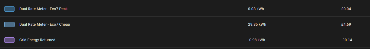
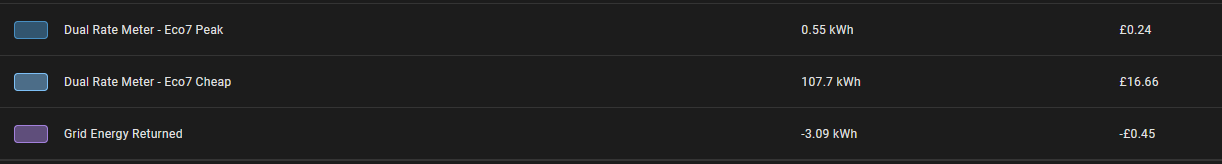
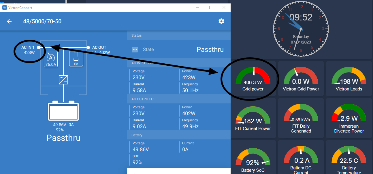
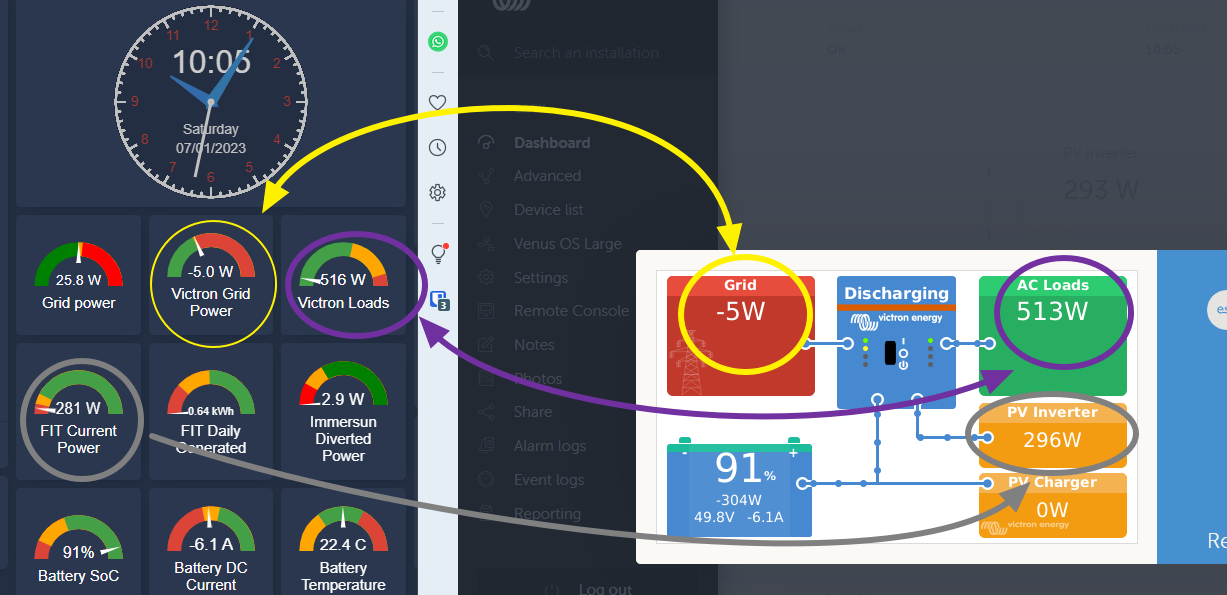
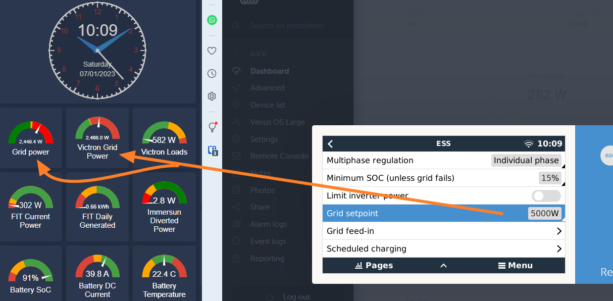
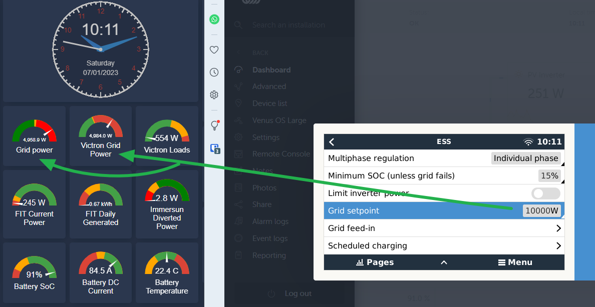
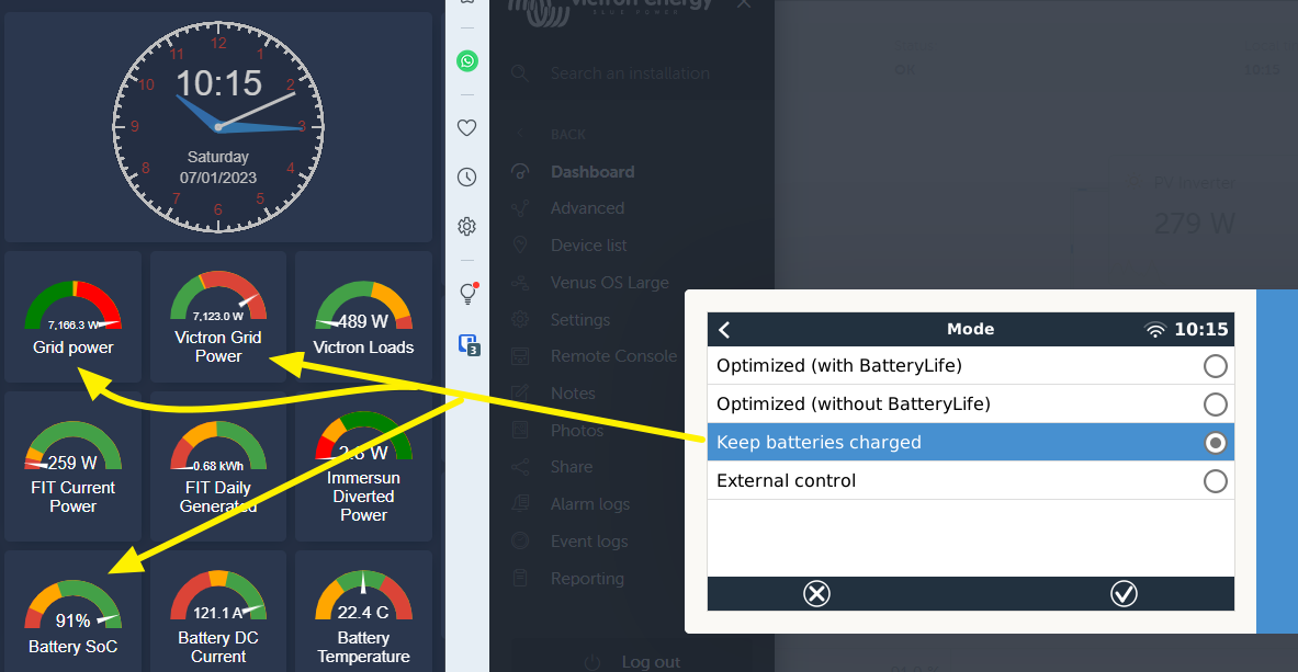
Overall it seems to work and is stable apart from the grid setpoint tracking. With it set to 10W it will vary between 50-100W when the general draw is about 1000W. With a 4000W draw it will bounce around between 100-300W and so on with higher loads.

Are the unit's fighting each other to balance the load?


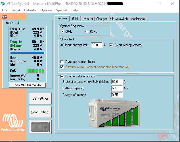
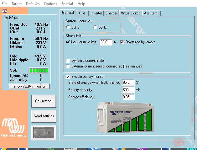
  • Running in ESS mode,
  • 6 x Pylon 3k Batteries
  • Smartsolar MPPT VE.Can 150/82 rev2
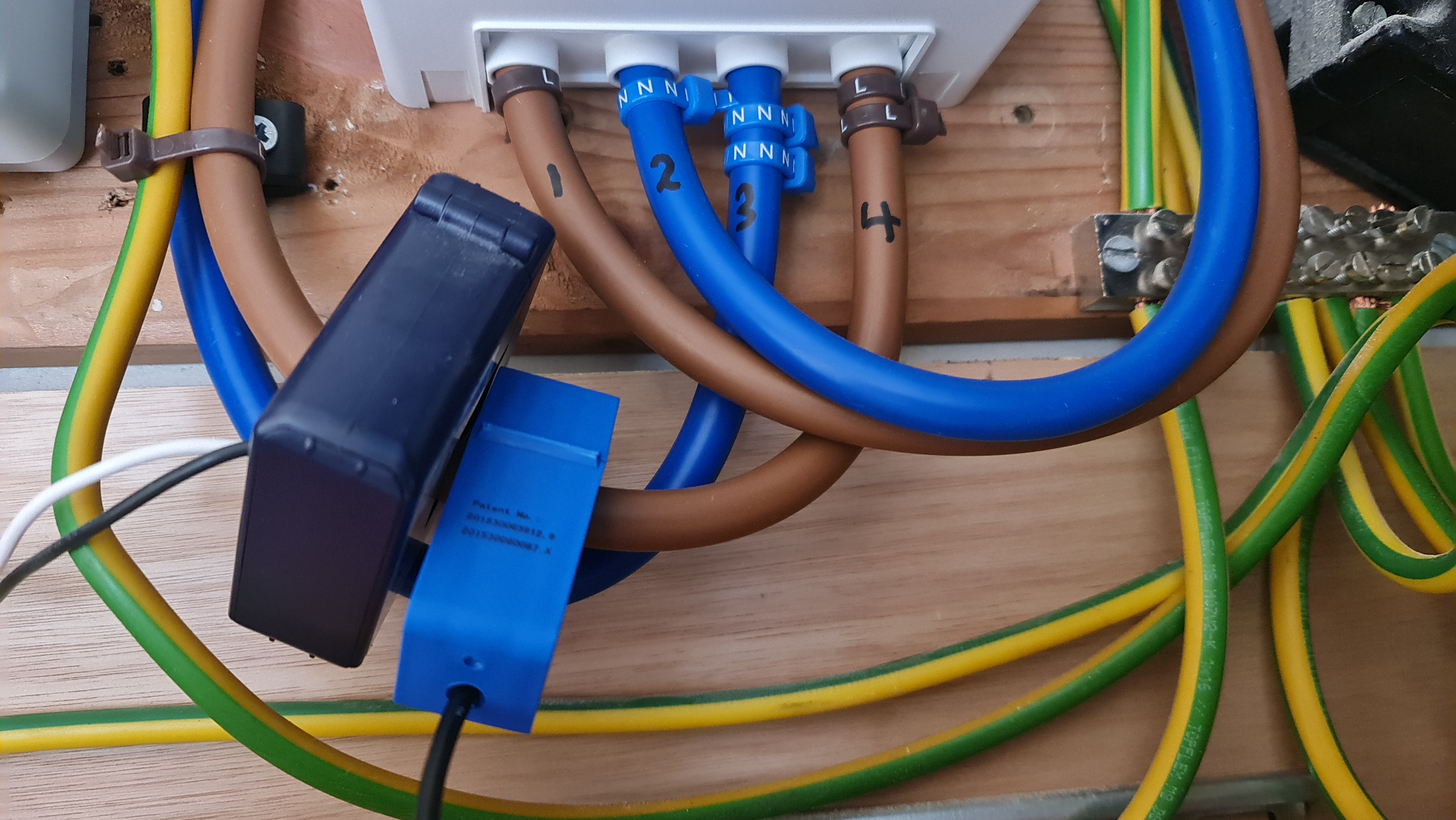
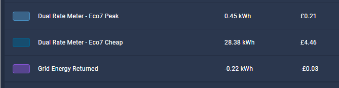
  • ET112 Grid Energy Meter before consumer unit
  • 240V single phase.
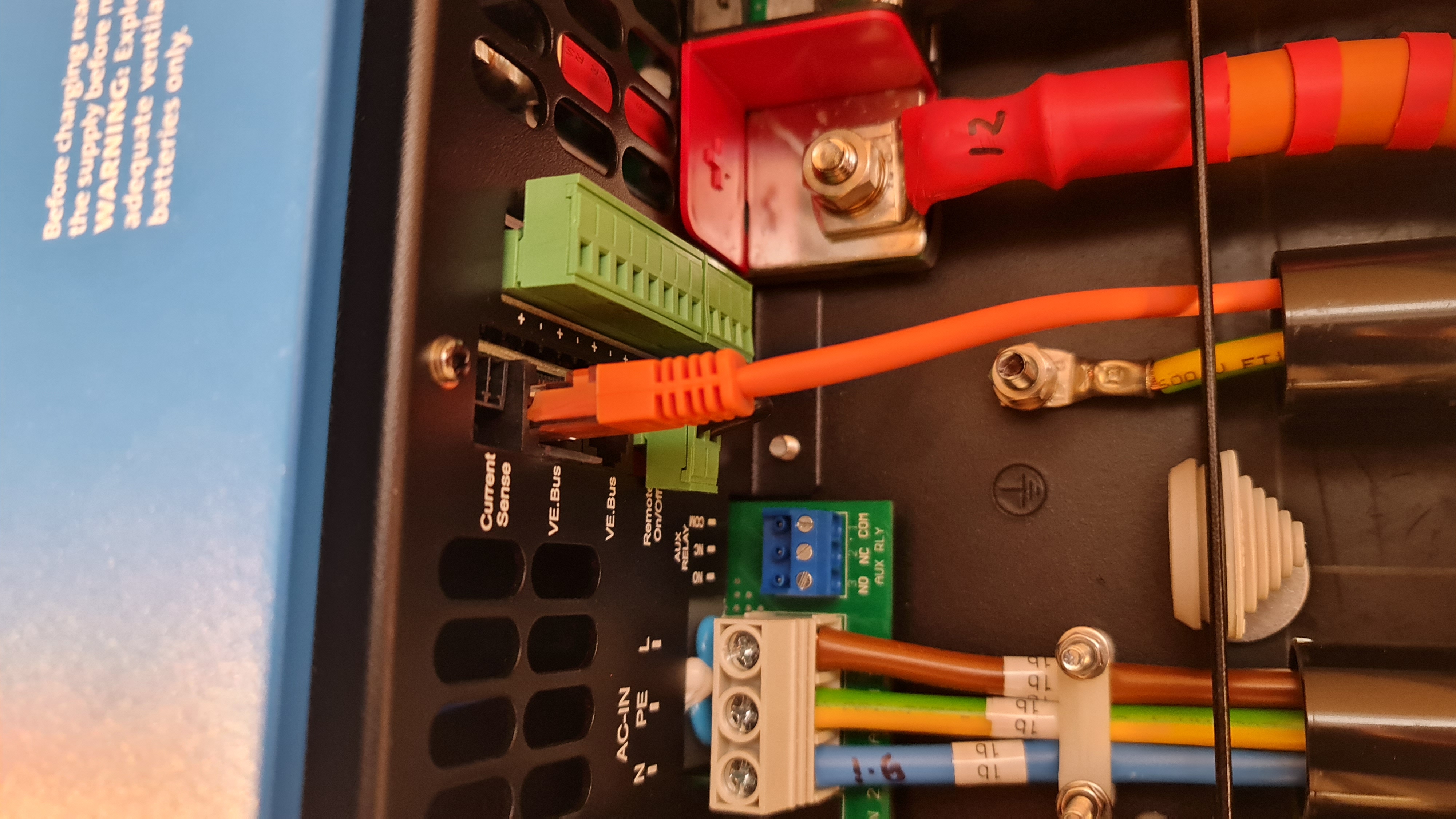
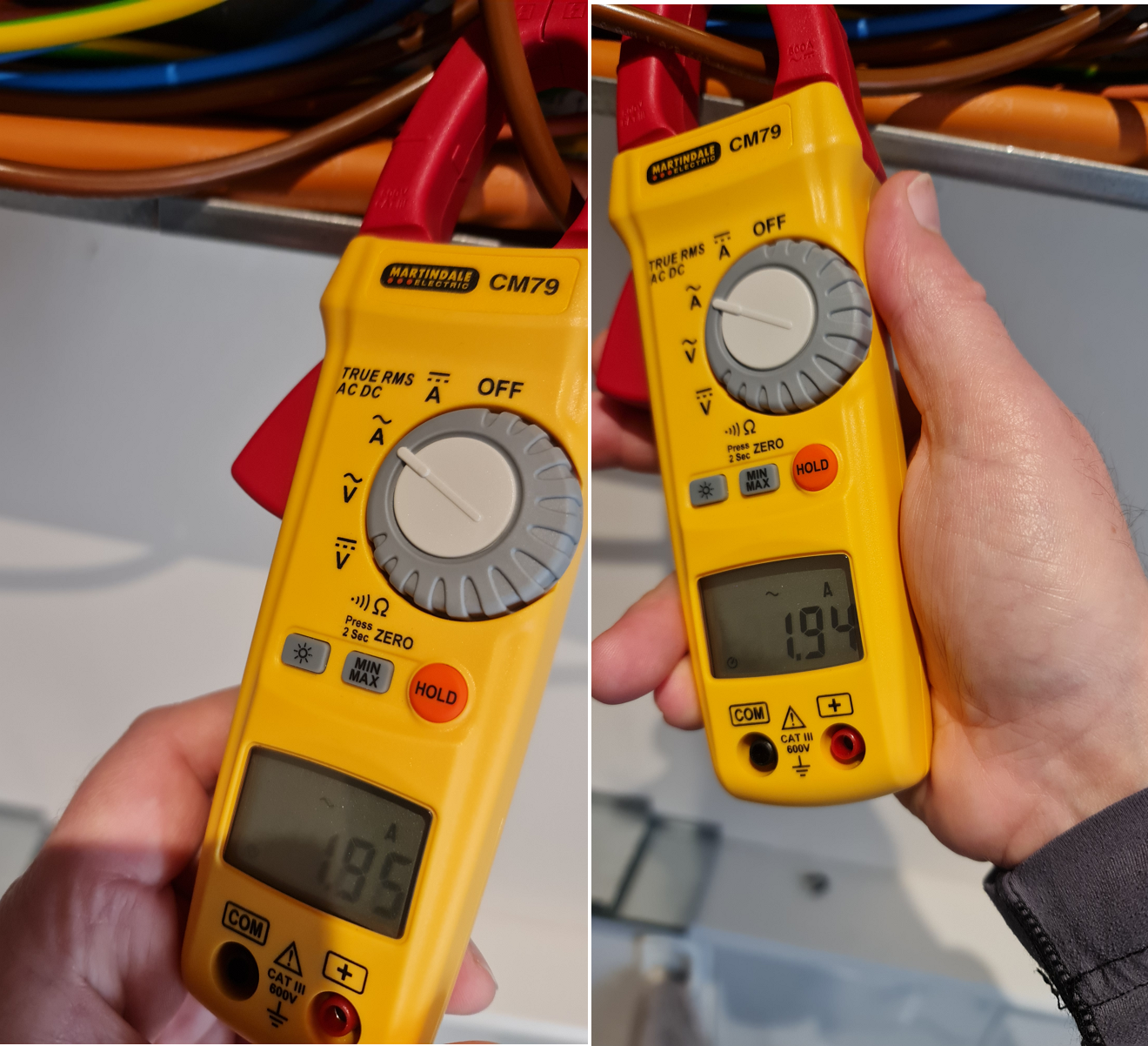
  • AC input is 20A MCB via 2.5mm2 cable to each inverter
  • AC Out 1 on both units connected together but not used which leads to an emergency outlet.
  • AC Out 2 are not connected at-all
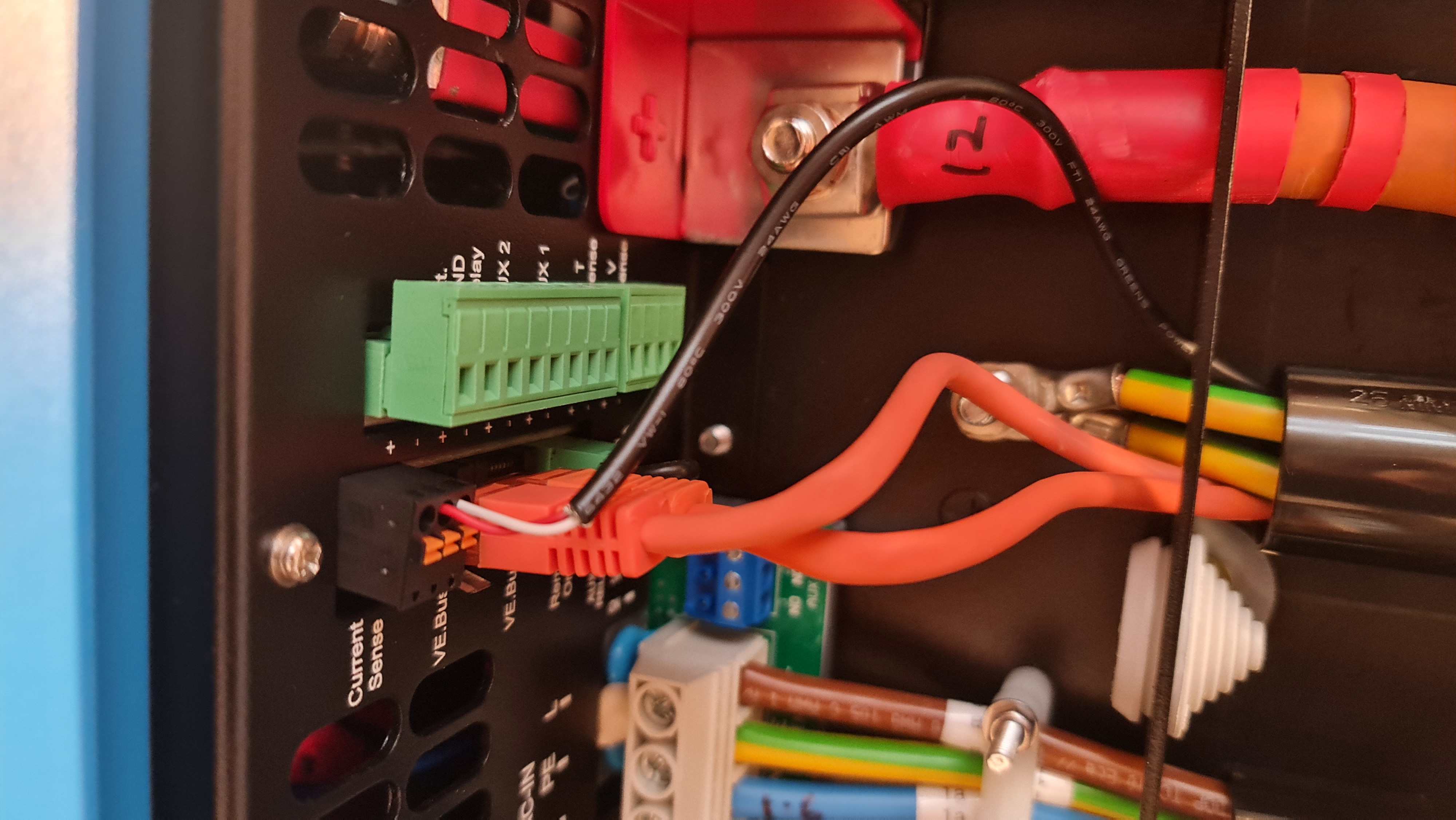
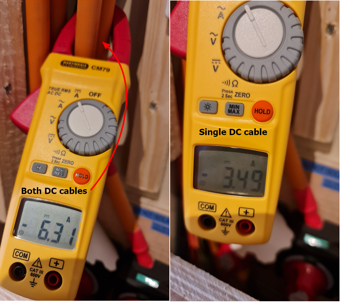
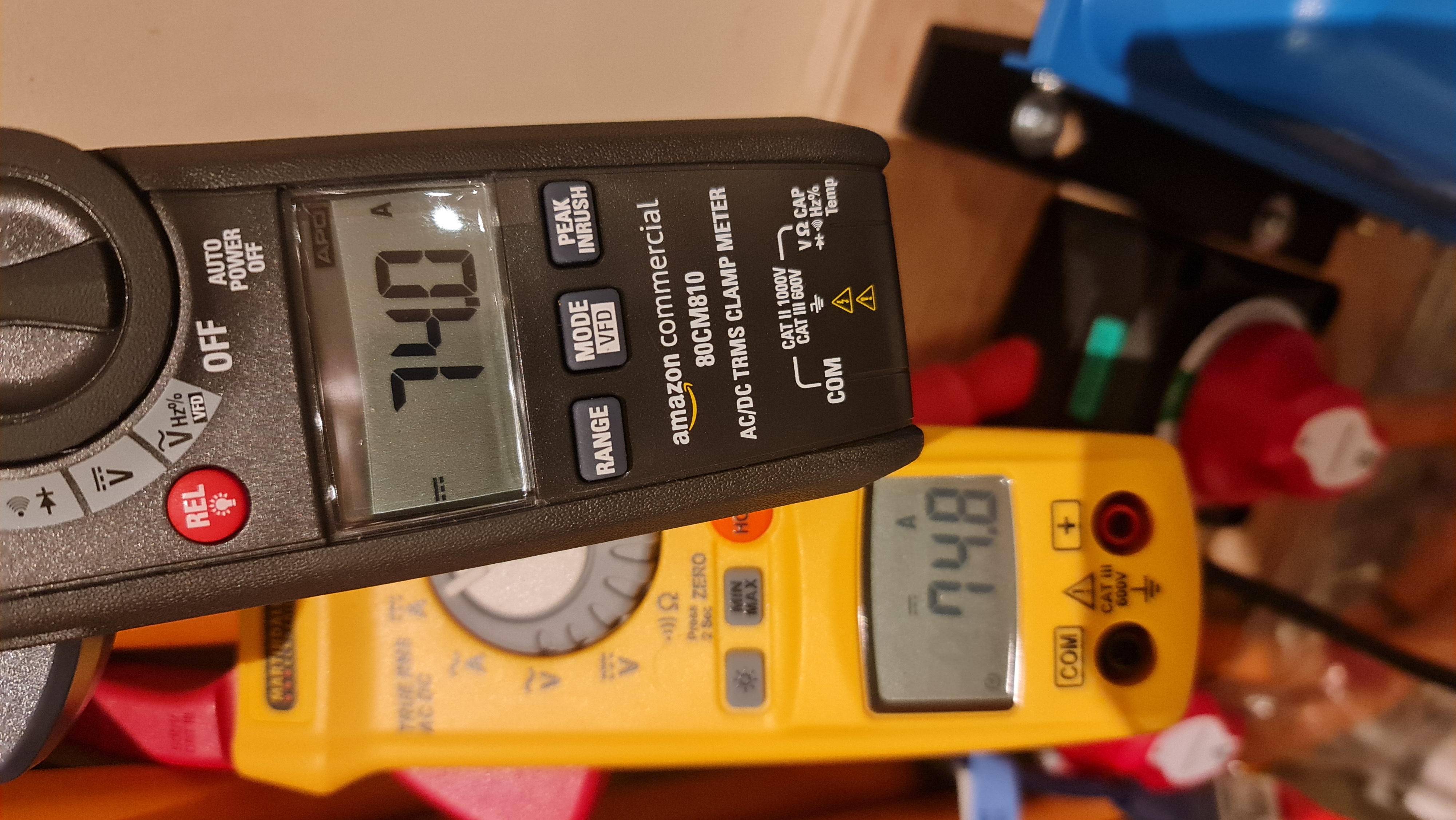
  • DC side is 70mm2 cable, identical lengths.


multiplus in paralleless grid setpoint not reached
2 |3000

Up to 8 attachments (including images) can be used with a maximum of 190.8 MiB each and 286.6 MiB total.

7 Answers
rata1 avatar image
rata1 answered ·

Hi.

I have a very similar issue but I started with a pair and power my house on AC_out1.

I can't get it to reasonably balance either. Over a 17hr day (I charge off grid at night and don't discharge) I pull about 50 Watt hours from the grid but discharge almost a kW/h from the batteries. Not ideal!

On full (test) load they are balanced within a few percent on DC and AC - but to me it sounds like they are fighting with each other being a pair in operation.

I posted another thread about whether a single external CT clamp was required/more suited on a parallel system on the input before the AC_in split but awaiting some replies.

2 |3000

Up to 8 attachments (including images) can be used with a maximum of 190.8 MiB each and 286.6 MiB total.

grantza avatar image
grantza answered ·

I have just finished with the installation and setup of the second 5kVA Multiplus-2 in my home installation. One 5kVA wasn't enough for our needs during the persistent load shedding here in South Africa. Hence the upgrade to add another Multi. The first Multi was purchased and installed back in 2019 and the newest one is less than a month old. I struggled initially to get them to work nicely together due to having a firmware version that didn't agree with the newer Multi (kept getting an Error 11 - VE.Bus Error: VE.Bus Error 11: Relay test fault). After updating both to version 500, everything is working 100%. However, I have noticed that the grid set point is not being met correctly (hence finding this discussion). With the setpoint at 30W I am constantly drawing 400W - 700W from the grid. I have also updated the Venus-GX to the latest firmware version, but this has unfortunately not improved on the situation. @rata1 - Please keep this thread updated should get any feedback regarding this issue?

2 |3000

Up to 8 attachments (including images) can be used with a maximum of 190.8 MiB each and 286.6 MiB total.

rata1 avatar image
rata1 answered ·

Your issue of drawing too much is the opposite of mine. I draw 10's of Watts but return up to/almost 10x that amount. I have tried various values from 100W to 0W on the setpoint and it is the same for me ;(

From Home Assistant yesterday

1672930417928.png

and the current week:

1672930619749.png


I think your problem might be related to a pairing of an older and a newer model.

I initially had two MP2s of late 2021. They were balanced to less than an Amp at a 70A forced charge when I commissioned them, so balanced (35A each DC leg). AC current was similarly balanced.

When one was returned a week later due to a fault it was replaced with a newer mid 2022 model (obvious change was the new CT clamp connector). With exactly the same cabling as it was a drop in replacement, it would never balance. Testing at a 70A charge as before, I was pulling 28A on one and 42A on the other so not balanced due to internal differences. Eventually the remaining 'old' one was replaced with one 8 weeks newer and it is perfect again.

It is required that all the cables are the same (exactly) as well as the units so if you are having these issues I would measure the current draw of each unit to see their imbalanced state. This may likely be the issue but expensive to resolve before investigating the feed back.

Not an expert just the pain I had.

My supplier was top notch and sorted the unit swaps - but they were bought at the same time explicitly for a pair so not the same for you.

Went through the FW upgrades prior to returning but did not resolve for me. I am sitting at 498 but the feed back issue is from install and several updates.

WRT the external CT clamp on the master with the slave CT connection removed on mine - it yielded proper operation and values apart from when I changed the grid set point to force a charge (it was half what I set). I only noticed this the day after when the batteries hadn't fully charged :(

If all I need to do is just double this number without any adverse affects and that is just a quirk I can live with it. But can't test until the weekend at the earliest and would have liked some official answer about it as don't want an overload or shutdown.

I expect a scheduled charge or keep batteries charged may have worked as no "values" are used, but I don't use that so didn't test. I'll try.


1672930417928.png (14.8 KiB)
1672930619749.png (15.0 KiB)
2 |3000

Up to 8 attachments (including images) can be used with a maximum of 190.8 MiB each and 286.6 MiB total.

Phil Gavin avatar image
Phil Gavin answered ·

It could be inherent in the feedback loop that when given an insubstantial target value close to zero, it may fall foul of the tolerance/response vs target ratio issues.

In other words, if you set a target of 10W, the error percentage when drawing a load that may swing 50W might mean the lagging response mechanism cannot cope. However, the error percentage and the feedback loop become more stable if you set a target of say 80W with the same load swing.

Try it and see if there is a slightly different target figure that gives you a better response.


1 comment
2 |3000

Up to 8 attachments (including images) can be used with a maximum of 190.8 MiB each and 286.6 MiB total.

nickdb avatar image nickdb ♦♦ commented ·
When I converted mine to parallel inverters the setpoint needed to be adjusted. It is logical as you have more than one device trying to cooperate. Also, you tend to increase loads, changes in load affects the setpoint.

Generally though, my total to/from grid numbers haven't actually changed that much.

0 Likes 0 ·
rata1 avatar image
rata1 answered ·

If that is to me not the OP - I already tried 100W and beyond and the result is the same in the feed back with the added negative that I draw more from the grid.

It is not the bouncing around that concerns me, it is the time taken to stabilise meaning too much is returned (in my case) as the mean is too high. The sampling of my smart meter misses some of what goes back (I don't get paid for that anyway) but the Victron's export figure is sampled less frequently so is inaccurate too.


Anyway, I did some changes this morning which I will post the results later. It is using a single CT on the master and open circuit on the slave as I did before but includes measurements from different grid set points etc.

2 |3000

Up to 8 attachments (including images) can be used with a maximum of 190.8 MiB each and 286.6 MiB total.

rata1 avatar image
rata1 answered ·

Hello,

So I made the same changes as I made before with a single CT and this time I measured the current of the pair and made some checks to see what was going on.

My goal, like a lot of others here, was to get the set point more accurate as I was giving too much precious winter energy away.

Here is what I did so you can judge for yourselves (and do at your own risk!) if it is something you want to try. So far it is working for me with only a slight inconvenience of doubling the set point when I want to manually charge at night and set how far open I want the grid.

First off I connected a CT clamp to the grid as it leaves my meter before being split into the two MP2s.


1673117723327.jpeg


Then connected that CT clamp to the Master MP2.

1673117827601.jpeg


Then removed the internal CT bridge connector so the slave effectively has no CT. If you have the older MP2 you would need to use a 3.5mm stereo jack plug I imagine to disconnect the internal bridge and isolate the connectors making it open circuit.

1673117777796.jpeg


Then, using VE Configure, I ticked the "External current sensor connected" and sent to the master MP2.


1673118038082.png


I checked it was not checked on the slave.

1673118098009.png


Then I opened VictronConnect to see the sensed power at the AC_in and AC_out whilst the Cerbo was disconnected.

The power circled on the VictronConnect is the same as my ShellyEM monitor reports in Home Assistant (not the AC_Out as it appears to). The ShellyEM reacts/samples far quicker to the Victoron, but the numbers are correct.

If you don't remove the slave's CT sensor by making it open circuit, you will see 50% added to the AC_Out which is not what you want. So if I had done that the AC_out would be around 600W. Ignore the "Victron Loads" on the top right.

1673118665465.png


I connected the CerboGX back up and compared what was going on in the remote console and HomeAssistant.

Below you can see the Grid, AC PV and AC loads are matching.


1673119052082.png

The DC side I only have one meter so by the time I swapped to the other cable the current went up a bit but proves to me that the DC is shared between the inverters.

Both DC cables and one of the others:

1673123233146.png

All good there then.

The problem I had before was that when I set the grid point to 5000W at night for charging only 2500W flowed and I was unsure (as it was early in the morning) if they were sharing the load.

As demonstrated below when the CT clamp is as above when I set 5000W I only pull half and it is the same reported by the Victron AC_In and my ShellyEM.

1673119363004.png

I measured the both AC_in's on each MP2 to ensure both were half each and not the master doing all the work;

1673123345371.png

Both looking spot on on AC_in. Checked the AC_out and it was similar (50-50).

So when I want to charge at off-peak at 5000W I set the grid point to 10,000W. Simples!

1673120289093.png

I will only be doing this in the winter and occasional top-ups in dull summer days and I do this with a script on Home Assistant based on next day solar generation so no big deal.

I checked the power draw when I enabled "Keep Batteries Charged" and although I expected 140A into the batteries I only got 120A. This may be that the batteries were already at 91% SoC.

1673120548343.png

If this isn't the case and 120A is my ceiling this is not big deal for me as I only charge my batteries (6 x US5000) at around 80A over night anyway.

When I commissioned these (and had another meter on hand) I was pulling >140A so I know it will do it and it is likely due to the 91% SoC the batteries aren't asking for more. Old photo from some months ago.

1673121091489.jpeg


Usually I give back between 600 to 800W/h a day.

After I made this change this morning I looked at my import and export in my Home Assistant (which is measured by the ShellyEM and confirmed by my SolarEdge meter and always more than the VRM). this is what it was at 11AM

1673121388452.png

The power imported (above) for my short tests doesn't show immediately but the time is now almost 20:00 and this is what it looks like now.

1673121471257.png

Much better - 70W/h!

I set the return cost at what I buy it at, but if it were my current day/peak unit rate of 46p it would be more significant over a year Besides the cost, it was not working the way I wanted!

I will monitor this over the next week, but other than doubling the manual setpoint it has no (measured) negative effect.

I don't know how the values are calculated by the MP2 to adjust the import/export but as the master and slave are supposed to act as "one", the 'grid clamp + zero' is exactly what it is using or returning so perhaps a future release of FW can be "more aware" of a parallel pair (or larger) and account for this in the setpoint calculations to allow this single external CT clamp only, for a more accurate control of the setpoint.

Hopefully this will help pave the way to that and keep more of my battery energy.

I would be interested in what results you get if you try it.

I am on 498 FW but it was the same on the earlier version I had on my older hardware MP2s.

Rob


1673117723327.jpeg (1.9 MiB)
1673117777796.jpeg (2.0 MiB)
1673117827601.jpeg (2.0 MiB)
1673118038082.png (52.9 KiB)
1673118098009.png (54.7 KiB)
1673118665465.png (142.2 KiB)
1673119052082.png (177.7 KiB)
1673119363004.png (133.6 KiB)
1673120289093.png (129.5 KiB)
1673120548343.png (128.8 KiB)
1673121091489.jpeg (2.2 MiB)
1673121388452.png (11.4 KiB)
1673121471257.png (11.3 KiB)
1673123233146.png (2.3 MiB)
1673123345371.png (1.9 MiB)
2 |3000

Up to 8 attachments (including images) can be used with a maximum of 190.8 MiB each and 286.6 MiB total.

graham-willsher avatar image
graham-willsher answered ·

Hi @rata1 @Guy Stewart (Victron Community Manager) ,

Having recently installed a second MultiPlus-II 48/5000/70-48 as per the OP, I went through the pain of setting the newest manufacture model as the Master and making sure that they were both running the latest firmware to come across the same GridSetPoint issue as you. I thought that I was going mad.

It seems that you have to enter double the value that you truely wish to achieve.

I know that this is a 'workaround' but do you know if this has been raised with Victron as an issue? As in theory if you are setting a GridSetPoint of 10000 that's what should be happening, not a halving of the value.

Regards,

Graham.

8 comments
2 |3000

Up to 8 attachments (including images) can be used with a maximum of 190.8 MiB each and 286.6 MiB total.

nickdb avatar image nickdb ♦♦ commented ·

Have you measured the systems under load to see if they are balanced?

If they aren’t, the setpoint won’t be either.

If the age and generational gap is wide, it will be even worse.

0 Likes 0 ·
graham-willsher avatar image graham-willsher nickdb ♦♦ commented ·

Hi @nickdb ,


Thanks for your reply.

The Master is a Multiplus II (model HQ2308JW3H2) and the slave is a Multiplus II-GX (model 22352YH9Z), both are running firmware 510, the latest one available a couple of weeks ago. Hopefully they are not to far apart in manufacturing to cause too many problems.

I have to acquire a pair of clamp meters so that I can carry out the actual testing whilst under load. Hopefully this will not throw up too many issues, but until I know that the system is balanced I will have to wait and see.

I only use the 'GridSetPoint' when I am exporting electricity so I only need to set it to a negative value, and I do not mind a slight fluctuation in the value as I know that loads change instantaneously and it is very hard to get an exact constant figure. This has only been an issue since I have had the second Multiplus in parallel. I am not quite sure why an unbalanced system would cause this much of an issue for the Multiplus', but I am not an expert in either Victron equipment or electricity.

My end goal would be for the 'GridSetPoint' to be a true repesentation of the value that we set. e.g. If I want to export at 5Kw setting the GridPoint to be -5000 should acheive that, the work around if fine for the moment, but if this is an internal issue that can be fixed carre would need to be taken for existing uses who have used this 'double the figure' fix, especially for me because I could be trying to export 10Kw where my agreed limit with UK Power Networks is 5Kw.

I will let you know how I get on with the balancing.

Regards,

Graham.

0 Likes 0 ·
nickdb avatar image nickdb ♦♦ graham-willsher commented ·
@graham Willsher I have a nodered flow that charts the individual performance and imbalance of a pair of parallel inverters. It requires some knowledge of nodered to use but is a useful tool.
0 Likes 0 ·
graham-willsher avatar image graham-willsher nickdb ♦♦ commented ·
Hi @nickdb,


If you would be willing to share your nodered flow, that would be great.

I had tried seeing if there was a way to get individual information from the invertors but could not see anything.

Thanks,

Graham.

0 Likes 0 ·
nickdb avatar image nickdb ♦♦ graham-willsher commented ·
Happy to, I will add a topic to modifications section tomorrow with my flow.
0 Likes 0 ·
graham-willsher avatar image graham-willsher nickdb ♦♦ commented ·
Hi @nickdb,

Thanks for the link.

I didn't realise that the information was 'hiding' in plan site in the MQTT messages. :), which I access for my Home Assisitant system.

Now that you have shown me where things are I can adjust what outputs I need to monitor.

Once again thanks for this. It does show that my system is not balanced and further work is required.

Regards,

Graham.

0 Likes 0 ·
nickdb avatar image nickdb ♦♦ graham-willsher commented ·
Glad I could help, invoice is in the mail ;)


0 Likes 0 ·