Hi guys,
I'm new user of Victron products but not I’m new to modern vehicle electronics or renewables. For a bit of background I am currently upgrading our Iveco Daily with a Cerbo GX, Lynx Distribution, Multiplus 12/1200/50, MPPT 100/50 and a Orion-TR Smart 12/12- 30 (plus other bits and bobs of course - BMV, Battery protect, isolators and fuses etc). Currently the system with be supporting an SLA battery but LiFePO4 or two are planned sometime in the future.
I know there are a ton of posts out there along the same lines but I have a query with the dedicated alternator signal wire for the Orion TR. Our MY2018 Daily have 210ps EURO VI engine with factory upgraded 210amp Smart Alternator (not start stop).
I have read through a number of the smart alternator DC-DC charger posts on this forum and others but nothing specific to the
To cut to the chase: -
Iveco provide a body connector which amongst other outputs provides a alternator status wire. On this wire I was expecting and ~12v when engine running/alternator charging and )v when alternator/vehicle battery is not changing.
I have not hooked up the Orion TR yet but as per installation and operation manual I ideally want to connect the status wire to the Orion TR H-pin and have it charge the leisure battery when alternator status wire is greater than 3v.
So with that in mind I have measured the following on the alternator status wire: -
0v – Engine off
2.55v – Engine running (note 14v+ measured across battery during engine running indicating alternator is charging)
I don’t have an oscilloscope but I don’t believe it’s a CAN signal
I need to do further testing as it’s entirely possible that ~2.5v is output when the alternator is not charging and 12v is output when the alternator/vehicle battery is charging.
Does anyone on board have any experience with eth Iveco Daily Body Connector (post 2018)?
Thanks.
asked
IVECO Daily 6 - Euro 6 - Smart alternator feed for Orion TR - 2.5v?
I believe it's covered in the Iveco body build manual, not sure of the name.
But if you don't get a clear answer, take a feed from the radio switched connection, and set the start delay in the Orion to a reasonable period. You might get an answer on the Iveco Tapatalk forum, but it's not getting many answers most of the time.
Many thanks kevgermany,
I forgot to mention that my first port of call was my local IVECO dealer (who also supplied the vehicle) Unfortunately they were of little use, apart from supplying the Bodybuilder manual.
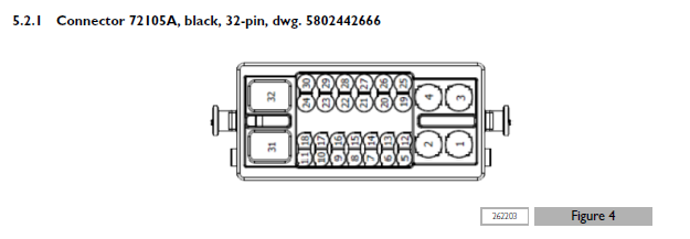
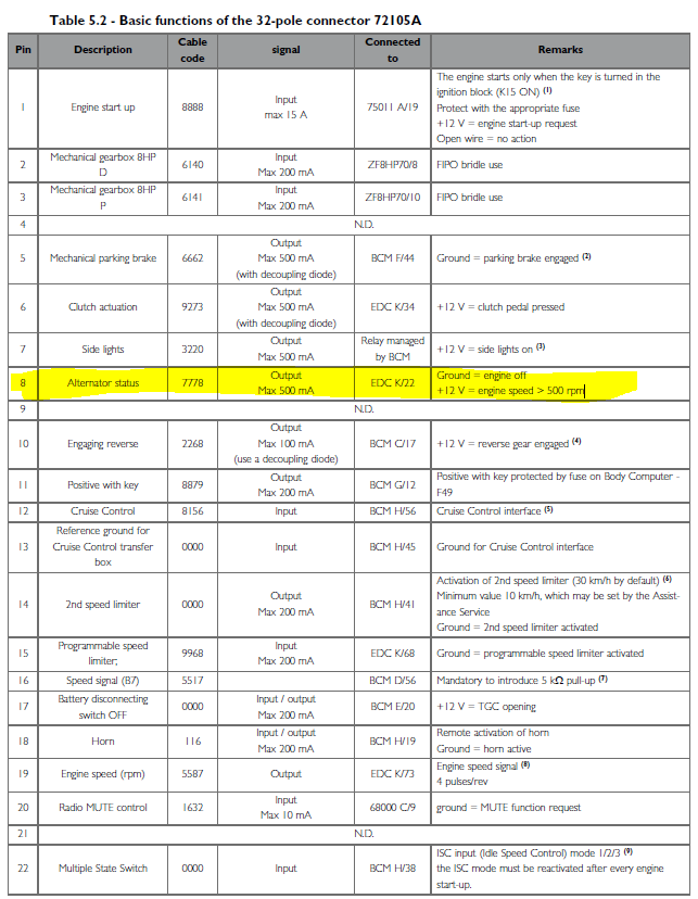
So I actually do have access to the 'Iveco Daily Body Guidelines for Bodybuilders'. It’s quite comprehensive in all regards but specifically it details the pin-outs for the new 32-pin bodybuilder connector of the late model Daily 6. I've extracted and pasted the pin-outs below - Note for anyone with an earlier Daily 6 - the 2014 - 2018.2MY chassis actually has two bodybuilder connectors, 20-pin and 12ipin respectively (same as Daily 3,4 and 5). This was combined into a single 32-pin connector from 2018.2MY (Vehicle chassis built at 9th June 2018)
However, thank you also for highlighting the option for a delayed start on the Orion, as well as a feed for the head unit I can also explore that option with some of the other functions available from the BB connector, vehicle moving status, handbrake off status etc, and implement the delayed start with that too.
In the meantime I plan to do a bit further testing on the existing ‘Alternator Status wire’. It may well be that with my observation that Alternator is charging the starter battery, the Engine ECU purposely might still be reporting the status to the BB connector as not charging. Perhaps the SoC of the vehicle battery has not reached the required threshold, or perhaps vehicle speed should be > 10kph/ SoC needs to be > 80% SoC/vehicle needs to be in gear etc.
Despite what the manual states there could be any combination of prerequisites required before that Bodybuilder Connector wire is pulled up to +12v. It’s a pity the guideline doc is not more explicit than just ‘+12 V = engine speed > 500 rpm’, but maybe it does not need to be.
However, even with the guideline docs are all aware in every industry how software/firmware updates can change the expected or documented of whoever device it maybe throughout its lifecycle. Often such changes or behaviour not communicated or documentation updated.
In any case once I have implemented working solution I will report back here for future forum reference.
Thanks again.
have you tried a pull up resistor? the data does show that it should go to +12, and from the table I'd expect that to also be able to source up to half an amp. Have you tried any of the other signals to see if they function as expected?
Best I know is that you should see +12V, as the manual and @Mike Dorsett say. I had something similar on my Daily IV, for reverse engaged. There is enough there to trigger a reversing camera, but I got a silly voltage reading on my meter.
I'd wire it temporarily and see what happens.