question

bazil avatar image
bazil asked

Clarity on BMV-712 connectivity parallel battery bank

Hello Everyone,

sorry if this question is somewhat amateur however could somebody please check my wiring intentions regarding BMV-712 Smart?

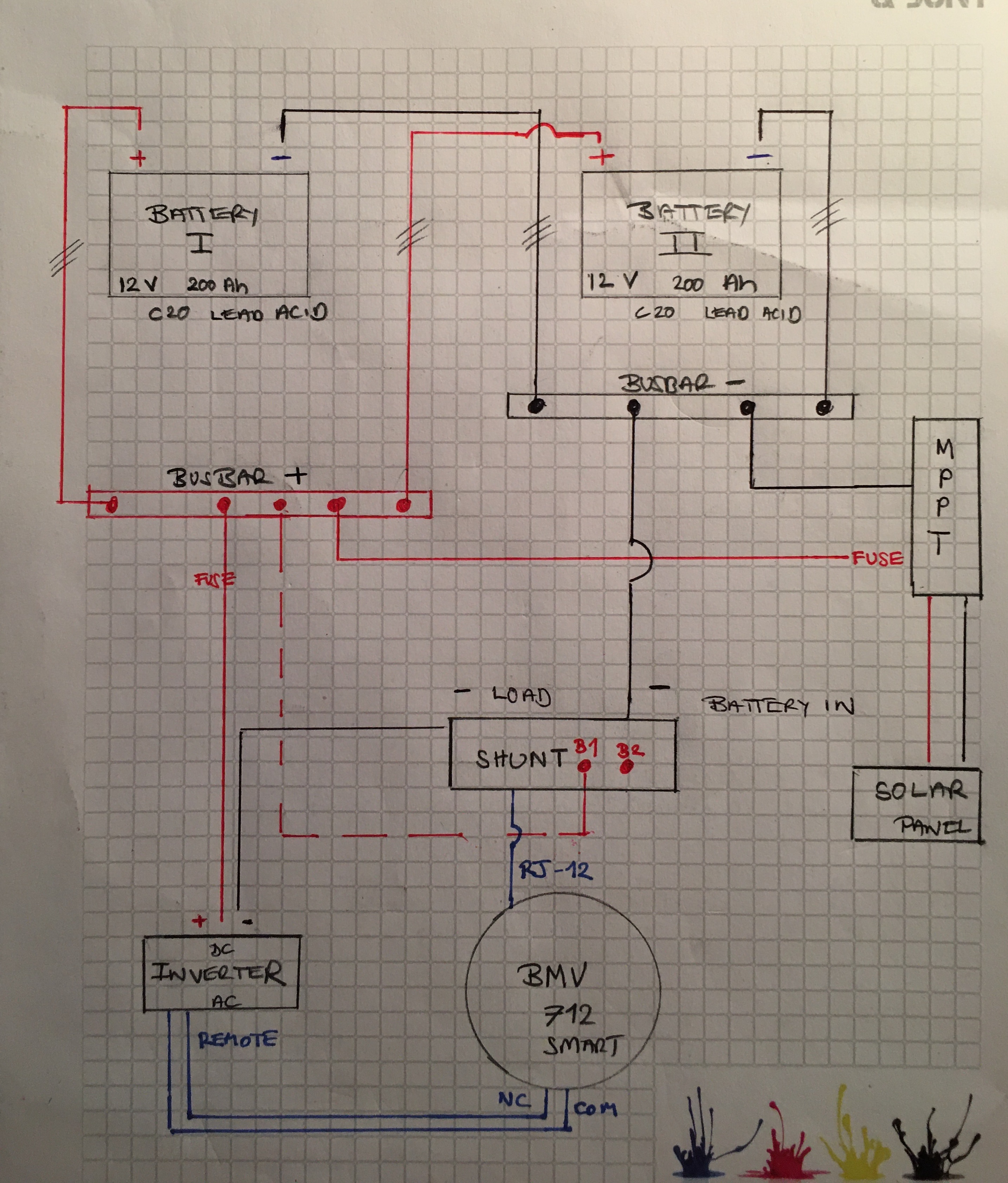
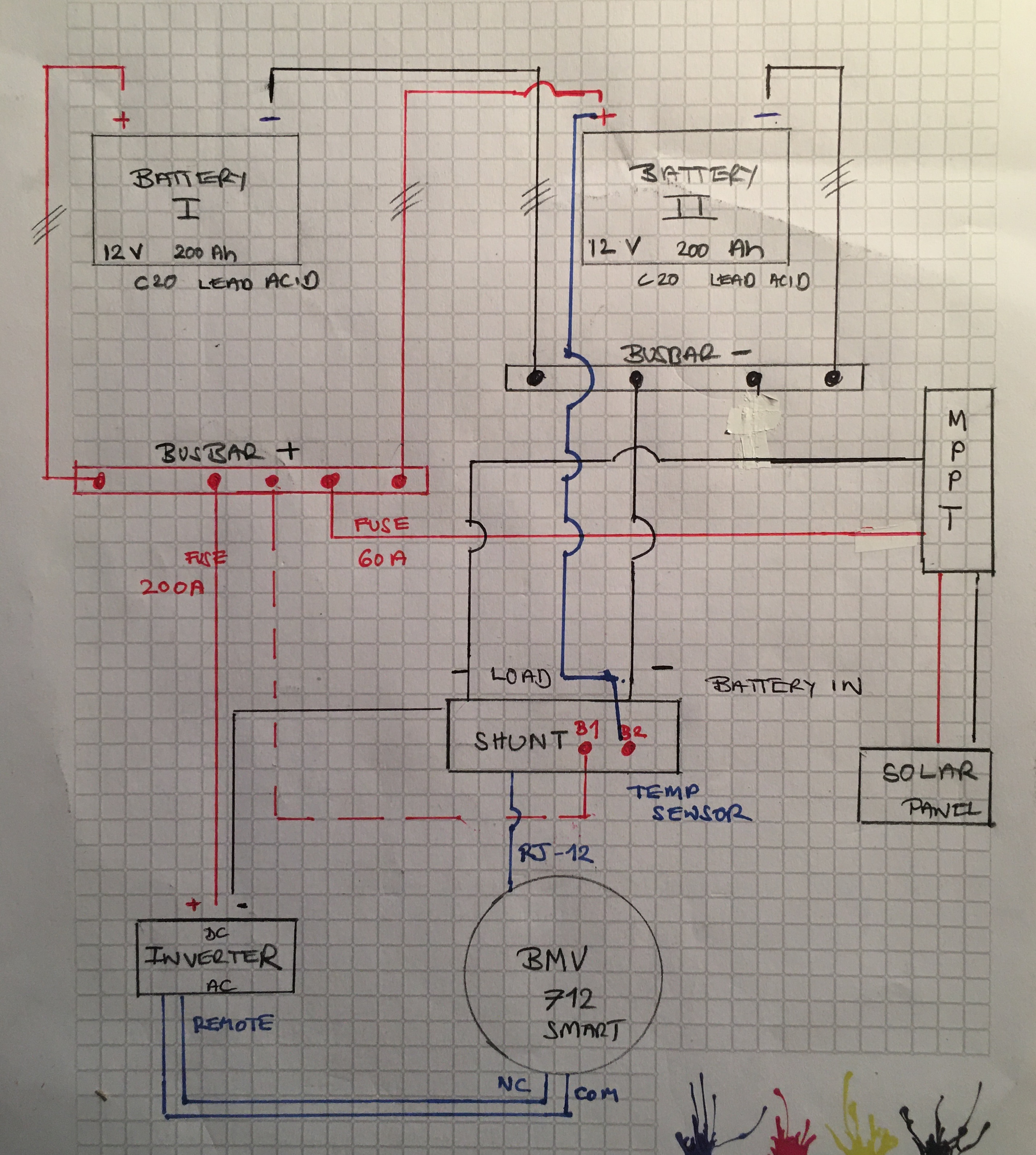
I have two 12 V | C20 | 200 Ah lead acid batteries connected in parallel via a busbar (cables of equal length to balance resistance).

If I've understood correctly, the shunt 'Battery -In' should connect to the negative busbar whilst B1 should connect to the positive busbar.

The battery capacity should be set to 400 Ah in the App.

If my understanding is correct B2 (Aux) can't be used to measure the Midpoint as my battery bank is 12 V; could however the temperature probe could be used to measure the batteries via the positive busbar?

Below is a sketch of my intended set-up.

Best regards

img-8382-copy.jpg

BMV Battery MonitorSmartShuntbusbar
img-8382-copy.jpg (1.7 MiB)
2 |3000

Up to 8 attachments (including images) can be used with a maximum of 190.8 MiB each and 286.6 MiB total.

5 Answers
klim8skeptic avatar image
klim8skeptic answered ·

2 comments,

you have to move the mppt's negative to the "system" side of the shunt.

move the temp sensor to 1 of the batteries positive post. better to keep an eye on 1 batteries temp, and hope the other matches, than measure the temp of a busbar.

2 |3000

Up to 8 attachments (including images) can be used with a maximum of 190.8 MiB each and 286.6 MiB total.

Kevin Windrem avatar image
Kevin Windrem answered ·

Also, the fuse on the MPPT should be at the busbar not close to the MPPT. Fuses (and circuit breakers) are there to protect wiring from shorts. If you short the wire going to the MPPT it will most likely burn up. If you locate a fuse in that line at the bus bar then that fuse will blow.


If battery to bus bar connections are long, then fuse each battery for the same reason.

2 |3000

Up to 8 attachments (including images) can be used with a maximum of 190.8 MiB each and 286.6 MiB total.

bazil avatar image
bazil answered ·

Many thanks to both of you for your sterling answers and suggestions; I have revamped my diagram to reflect the changes. Battery to bus bar connections are 50 cm / 20"

Best regards

img-8384.jpg


img-8384.jpg (1.6 MiB)
2 |3000

Up to 8 attachments (including images) can be used with a maximum of 190.8 MiB each and 286.6 MiB total.

Kevin Windrem avatar image
Kevin Windrem answered ·

Currently you only show two batteries, and only the inverter and the MPPT so it is the same number of connections on both sides of the shunt.

If you don't plan on future expansion, then you could eliminate the negative busbar and use the shunt as the connection point for batteries and loads. One or two connections to each post should be pretty easy.

For best current balance between batteries, also make sure the positive connections between battery and shunt are the same length and the negative connections between battery and shunt are the same length. It is not necessary to make the positive and negative lengths the same.

Busbars make it easier for more than one or two connections. So the positive busbar already makes sense.

Another simplification: jumper the two batteries to each other, then take the positive off one battery and the negative off the other. That keeps the current balanced between the two batteries. This only works with two batteries. Some people do more than two batteries this way but it's not possible to exactly balance currents to all batteries without a common point (busbar).


2 |3000

Up to 8 attachments (including images) can be used with a maximum of 190.8 MiB each and 286.6 MiB total.

bazil avatar image
bazil answered ·

Thank you so much once again for your help I really appreciate it! Excellent idea regarding the negative busbar - I never would have thought of this.

2 |3000

Up to 8 attachments (including images) can be used with a maximum of 190.8 MiB each and 286.6 MiB total.