question

karwas avatar image
karwas asked

How to control MPPT (VE.Can) to stop charging at certain SoC level e.g 80%?

Hello,

TLD;R - I would like for a piece of mind and health of a LiFePO batteries implement a charging strategy similar to e.g. Tesla cars: Charge only to specified SoC, let's say 80%.

My current setup includes:

  • LiFePO bank monitored and controlled by REC BMS,
  • Lynx Shunt 1000A VE.Can shunt
  • SmartSolar Charger VE.Can 150/70
  • and Cerbo GX

among other components.

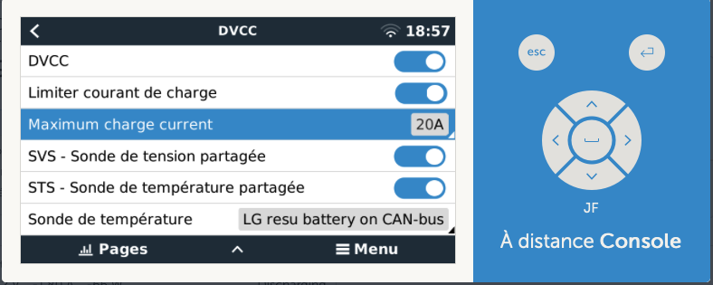
In current setup, if I understand it correctly, REC BMS is periodically sending a frames on CAN Bus
advertising current SOC (among other things), and effectively controls MPPT to slow charging
when SOC reaches 98% and stop charging when SOC is equal 100%. This is a behavior
I can observe on both Cerbo GX and VRM portal.

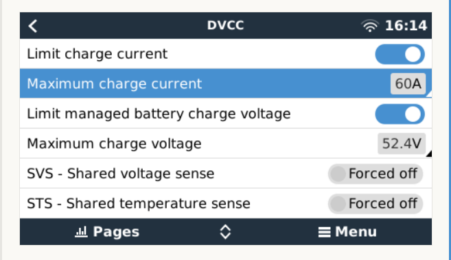
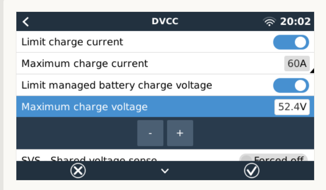
I would like to stop charging at 80%, both for extending battery life, and for pice of mind,
that when boat is unattended, some fluke in SOC calculation would make MPPT overcharge
batteries. Is it possible?

Thanks,
Przemek
S/V Festina Lente

MPPT ControllersVE.Can
2 |3000

Up to 8 attachments (including images) can be used with a maximum of 190.8 MiB each and 286.6 MiB total.

7 Answers
snoobler avatar image
snoobler answered ·

Trying to short charge LFP to lower SoC has negligible value and can actually cause problems. Failing to charge the cells into the BMS balancing range will allow cell SoC to deviate causing capacity loss. It's been documented that Battleborn batteries have lost 50% capacity due to failing to charge to the balancing range. By holding them at the balancing voltage for about a week, the capacity can be recovered, but this has the battery out of service for that.


Additionally, using voltage to target SoC with LFP is a losing proposition 99% of the time.


If you want maximized cycle life, simply charge your LFP batteries to 3.45V/cell (13.8V, 27.6V, 55.2V) with a two hour fixed absorption, tail current disabled. Float at 3.375V (13.5V, 27V, 54V).


It both maximizes cycle life, and it minimizes the potential for cell imbalance.

2 |3000

Up to 8 attachments (including images) can be used with a maximum of 190.8 MiB each and 286.6 MiB total.

hjohnson avatar image
hjohnson answered ·

So've been looking at something related to this too, also using the REC BMS. However, the way you understand things isn't quite right (assuming you're running DVCC, which you should be). In this situation the REC snds out messages saying "I want x A feed" and the charging sources will do that.

From what I can tell, you can configure the CHAR command on the REC and that will limit the charge to it. These commands need to be sent to the BMS via RS485, rather than over the CAN Bus. I'm looking at implementing something via Node Red. the idea is that I can let the battery stay at roughly 80% at the dock and while doing daysailing, but if I'm going out on an overnight or longer trip, I can remotely log in and kick it up to 100% charge.

1 comment
2 |3000

Up to 8 attachments (including images) can be used with a maximum of 190.8 MiB each and 286.6 MiB total.

karwas avatar image karwas commented ·

Thanks so much for your answer.

I still have few questions and comments.

According to REC Active BMS documentation, "CHAR" command can be used to
set (or inquire settings) of individual Cell End of charging voltage (page 12 of pdf manual):


CHAR? Or
CHAR x.xxx
Cell End of charging voltage
Returns float voltage [V]
2.0 to 4.30 V


Unfortunately, charging characteristic of LiFePO batteries has very little correlation
between cell voltage and state of charge. In my case I have observed that with given
charging current, voltage on cells stays constant (+/- few mV) until cell is nearly fully charged,
and then rapidly increases in the last few minutes. So any detection of SoC based only on
cell voltage measurements alone is fairly inaccurate. If, on the other hand, objective is to detect
when individual cell is approaching 100% SOC, and based on such detection, start balancing
procedure, and eventually terminate charging process, simple voltage measurements are sufficient.
The actual charging algorithm is actually very nicely described with all details in "Battery Pack's
Charging Algorithm" section of the REC manual.

The configuration challenge for me is how to configure accessible parameters to deploy this
ramped-down charging process and eventually stop it at 80% SOC.

I think that I could handle software/hardware side of this project using some RS485 dongle connected to spare USB port of Cerbo GX, but I don't know what software knobs
I would need to turn to make charging algorithm triggered by SOC and not cell voltage.

---

And yes, I do run DVCC, although I need to do some reading about it.

What is confusing me it is that it seems like REC BMS would be perfectly capable
to control MPPT via CANBUS, even without Cerbo GX. But I need to learn more.

---

What seems to be a promising feature, is ability to use SoC to start/stop generator:

https://www.victronenergy.com/media/pg/CCGX/en/gx---generator-auto-start-stop.html

I would rather avoid running extra wires to use relay to shut down MPPT so I am still
looking for the solution using my existing bus topology (CANBUS for inter-device comms,
and RS485 for configuration, logging and troubleshooting)


Thanks,
Przemek
S/V Festina Lente

0 Likes 0 ·
hjohnson avatar image
hjohnson answered ·

The other way you might be able to attack this is using node red on the cerbo. Watch the SOC as reported from the battery, and when it exceeds 80% disable your charging sources. It’s not elegant (and won’t likely work with my Wakespeed) but I think i should be able to disable charging from my mppt and multiplus.

1 comment
2 |3000

Up to 8 attachments (including images) can be used with a maximum of 190.8 MiB each and 286.6 MiB total.

karwas avatar image karwas commented ·
I have not mentioned it in my original post, but I also have Wakespeed WS500:-)

But whenever Balmar is making power under a Wakespeed supervision,
I am on board (or some other capable crew member), and I hope we can
react if see that batteries are on the verge of overcharging.

MPPT is a different story as it is commonly used unsupervised in marina.

0 Likes 0 ·
kevgermany avatar image
kevgermany answered ·

Some background to take into account:

Always charge to battery makers recommendations

There are different chemistries in lithium batteries, with different charging needs. Some of it is covered in this Tesla manual page.

https://www.tesla.com/ownersmanual/model3/en_jo/GUID-7FE78D73-0A17-47C4-B21B-54F641FFAEF4.html

In particular LiFePo4 should be fully charged.


3 comments
2 |3000

Up to 8 attachments (including images) can be used with a maximum of 190.8 MiB each and 286.6 MiB total.

karwas avatar image karwas commented ·

Very interesting indeed.

My boat battery bank is made of 12 individual prismatic cells 280Ah each in 4s3 configuration.

Unfortunately I don't have any good technical data about those cells, as I have got them
from Aliexpress (Chinese eBay).

What I know about charging LFP (LiFePO4) batteries I have mostly learned
from this excellent blog:

https://nordkyndesign.com/category/marine-engineering/electrical/lithium-battery-systems/

and specifically this:

https://nordkyndesign.com/charging-marine-lithium-battery-banks/

and discussions with friends.

---

I am really confused about Tesla manual you have shared, because in my model Y
whenever I use the slider for charging limit over 90% or so, it warns me that I should
consider lowering charging limit to improve battery life. And according to my VIN,
seventh character is "E" which indicates LFP batteries.
^^^^^^^^^^^^^^^^^^^^^^^^^^^^^^^^^^^^^^^^^^^^^^^^^^^^ correction, I was wrong
seems like "F" is for LFP, "E" is for NMC

Please also bear in mind that I have used Tesla just as an example of "wanted"
charging behavior - I trust (somehow) Tesla engineering much more that my own
Frankenstein solution with all the vendors and cheap Chinese cells :-)


0 Likes 0 ·
klim8skeptic avatar image klim8skeptic ♦ karwas commented ·
0 Likes 0 ·
kevgermany avatar image kevgermany ♦♦ karwas commented ·
Looks like all the info you need is in your second link(plus a ton more, information overload rules).


Distilled down it comes to what @shaneyake said. Pick a voltage set this as absorption. Then set float a bit lower, which will stop the charge until battery voltage drops. And set tail current. Also check the REC BMS docs to see how/when cell balancing kicks in. As he said, this needs to happen.
0 Likes 0 ·
shaneyake avatar image
shaneyake answered ·

The simplest way to do this is to limit charge voltage in the DVCC menu.
You could just set the limit to 54.4V which is 3.40V per cell. Or whatever voltage archives your desired SOC.

But something to keep in mind is that you really want to top balance the LFP cells and that isn't really going to happen if you go too low on the SOC. LFP is not like lithium-ion batteries that typically degrade at higher SOC's, LFP is happy to sit at 100% all day long, especially if your 100% is like 3.45V per cell.

2 |3000

Up to 8 attachments (including images) can be used with a maximum of 190.8 MiB each and 286.6 MiB total.

ted avatar image
ted answered ·

I found only that you could set the Maximum charge current to zero


1681481697707.png


1681481697707.png (69.2 KiB)
2 comments
2 |3000

Up to 8 attachments (including images) can be used with a maximum of 190.8 MiB each and 286.6 MiB total.

kevgermany avatar image kevgermany ♦♦ commented ·
What happens when you click on the max charge voltage line?
0 Likes 0 ·
ted avatar image ted kevgermany ♦♦ commented ·

You can change it. For Pylontech Victron suggest 52.4V


1681581806709.png

0 Likes 0 ·
1681581806709.png (54.5 KiB)
titi avatar image
titi answered ·

Hello Ted, thanks for this information. I am also trying to limit charging whenever the SOC is up to 93%. I went to the DVCC menu on the Cerbo, I can limit the charging current, but I can't see the "limit managed battery charge voltage" option. Attached is a picture of the DVCC options I can see.

Is there something I can do to access this voltage option ?

Thanks for your feedback

capture-decran-2023-11-09-a-185722.png


2 |3000

Up to 8 attachments (including images) can be used with a maximum of 190.8 MiB each and 286.6 MiB total.

Related Resources

Additional resources still need to be added for this topic

MPPT Product Page

MPPT Error codes

MPPT 150/60 up to 250/70 Manual