question

robsimons avatar image
robsimons asked

Multiplus II GX ESS + micro inverters + battery + SE inverter

Hi,

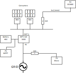
I have a question about how to best connect two separate PV setups to the multiplus II gx. One of the PV setups is a solaredge3680 system which should not be a problem since the MP can connect to it through the ethernet network. I'm going to connect these through a 16A fuse.

The other setup consist of multiple micro inverters from APS systems DS3 880 inverters. The total of these should fit on a 16A fuse as well.

Since I read in other topics that the micro inverters are difficult to manage from the MP system and that these are best put on the AC IN port of the MP so the MP can shut them off entirely if the grid fails and too much solar power is generated by the setup.


setup.png


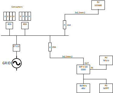
I'm also considering to replace one (or more) of the micro inverters by a MPPT 48V inverter directly connected to the battery link. This in case the battery runs completely empty and I need direct 48V charge to restart the entire system.


My questions:

1) Am I correct that the output of the MP II GX will never exceed the 4000W in this setup? So am I safe in using a 3x 2.5mm2 cable (25Amp max) and using a 20A fuse?

2) Is there an alternative for the ET112 to use that uses ethernet or someting? How stable is a zigbee connection between the ET112 and MP? Distance is about 60 meters including through two outside walls.

3) Is it overkill to install a (small) MPPT inverter to be able to recover the battery in case of depletion? (Perhaps it is .. I do have a small generator at hand as well).

4) Is the setup as depicted in the drawing safe with regards to fuse and cable usage?

5) Is there anything I'm missing?


Regards,

Rob.

multiple inverters
setup.png (6.5 KiB)
2 |3000

Up to 8 attachments (including images) can be used with a maximum of 190.8 MiB each and 286.6 MiB total.

1 Answer
robsimons avatar image
robsimons answered ·

After some more reading it appears that in an ESS setup I need to be able to disconnect the grid when there is a grid failure. This can be achieved by placing the MP-II between the grid and the consumers. The MP-II will then be able to completely terminate the grid connection through the double relais on the AC-IN port.

The micro inverter PV setup can then be connected directly to the grid as well and will completely shut off when the grid fails. This is necessary because it can't be controlled by the MP-II.

setup-t2.png

Some additional questions ..

1) Is it normal to directly connect the MP-II to the main power switch (i.e. after the meter)? Or should there be an additional fuse installed? The MP-II is in another cabinet from the main power so I need to install a cable to and from the MP-II. This would be a 3x4mm2 cable I suppose since it would carry 35A for the entire house.

2) I suppose I no longer need the ET112 now since the MP-II will do the measuring, correct?

3) Can the AC-OUT-2 be used for the micro inverter PV's? So that in case there is not enough power in the main PV (top picure) the micro inverter PVs can be added to the total by the MP-II ?


I would really prefer to have an ESS system with the MP-II connected through a single connection uplink. That way I could install all equipment in my shed (where the PVs are as well) instead of in the house. Do I really need the separate extra anti-island box for that?


setup-t2.png (5.9 KiB)
2 |3000

Up to 8 attachments (including images) can be used with a maximum of 190.8 MiB each and 286.6 MiB total.

Related Resources

Additional resources still need to be added for this topic