So when reading the Wiring Unlimited doc, it shows connecting up multiple batteries in parallel in a configuration where your pos/neg taps come from opposite ends of the busbar like on page 19 and 26: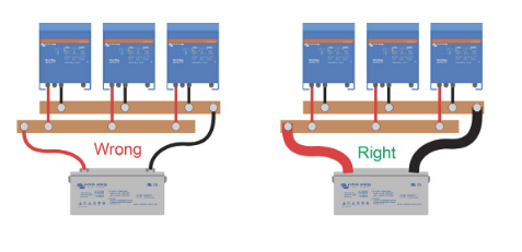
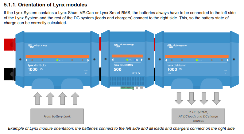
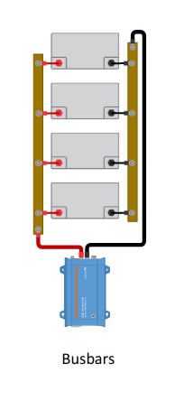 Now, how does this vibe with the typical Lynx install where each battery is connected to the bus and then the ends of the bus are connected to the next Lynx Component using the nearest corners instead of the opposite corners. In the standard system below it would look to me that potentially all the power is going to preferentially come from the first then 2nd, 3rd, 4th battery instead of spreading it equally. Seems like a bit of a departure from previous recommendations.
 I'm definitely giving Victron the benefit of the doubt on this. Maybe the balancing is not a big deal and they will self correct over time, or maybe the bus bars are high enough quality that it doesn't really add any extra resistance for the ones on the end. It may be why they stress to use exactly the same links for each battery when connecting to the bus bar.
Anyone want to shine a bit of light on this topic?
PS. I love the Lynx system and pretty much all the Victron products. Just trying to wrap my head around something that has been nagging me for a while.