question

caver avatar image
caver asked

Electric propulsion sailing catamaran - battery system design

We are designing a 52' performance sailing cat and would appreciate any advice or links to other resources in planning our system.

Propulsion and galley services all electric. Motors 2 x 15kwh ( DC 48V) + house loads DC 24V + 240V Ac via inverter.

Supply side planning a battery bank of circa 18kwh, 16kwh 48V DC Gen set, Solar around 2kw + what ever regeneration we get.

As a performance catamaran, weight is an important consideration, both in terms of optimal placement and total kg. Am reflecting on battery placement and whether to centralise or decentralise. Desirable to locate batteries as close as possible to load and distribute weight. With an elec motor in each hull would make some sense to create 2 separate battery banks for Elec Propulsion + one for house loads. Reduces heavy cabling & Vd, provides redundancy but adds complexity & cost -presumably would need 3 BMS, one for each bank + run charge sources to 3 places?

Im also puzzled about how 3 separate banks would interact in terms of relative charging and separate SOC?


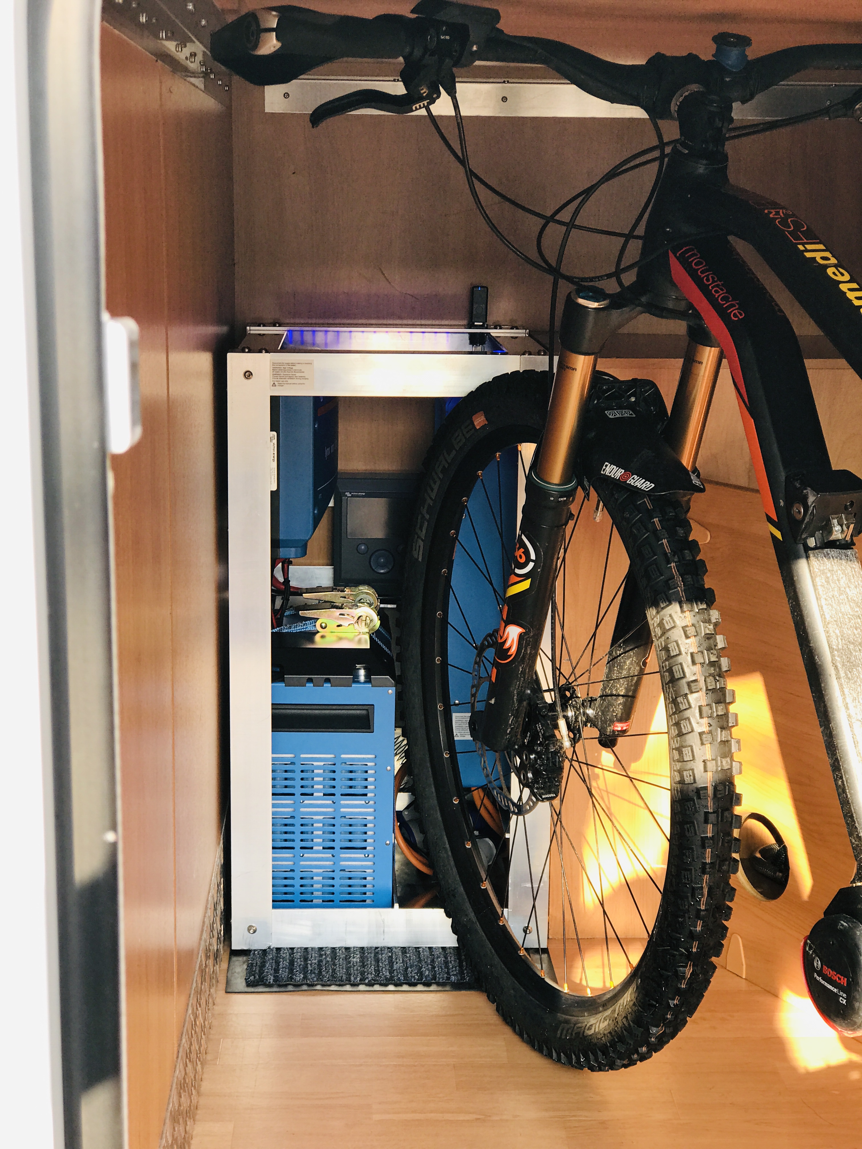
Finally anyone have experience with the Victron Lithium-Ion HE Batteries ? They are Lithium Nickel Manganese Cobalt Oxide (NMC) technology, energy density at 180kw/kg is outstanding, 24V, air cooled but with only IP22 rating. Apparently this technology is used in power tool and EV applications.

Yes expensive but if weight matters (and it does to me) possibly worth it. Wondering if they are robust enough for a sailing cat. Certainly marketed as "Marine" but the IP22 rating not great.

I can see advantages in assembling a full Victron system from Batteries, BMS to Inverter aside from expense.

Appreciate any comments, guidance or links to resources that can assist.


Thanks in advance.

batterysystem design
3 comments
2 |3000

Up to 8 attachments (including images) can be used with a maximum of 190.8 MiB each and 286.6 MiB total.

John Rushworth avatar image John Rushworth ♦♦ commented ·

Hi. I use liFePO4 in my electric boat but for the weight reasons you state I'm using NMC in my motorhome. Here's a modular system I made which I'll blog about on the Victron blog in due course. I'm using DVCC for charge control with the BMS and CCGX. Works great. Also note the energy density is in fact either 75% DOD or 100% so either 3.78kWh or 5.05kWh useable with the 200Ah. I know the datasheet says 80%. These DODs are called default and performance and can be set with the BMS tool, which requires this cable. https://www.victronenergy.com/accessories/canusb-interface ASS030532010 CANUSB interface . See Victron Professional for the Lynx ION BMS and more info. I'm just waiting for the cable to test. If planning an electric install consider the C charge and discharge rates which will determine your series/parallel connections.

0 Likes 0 ·
img-7980.jpg (2.9 MiB)
caver avatar image caver John Rushworth ♦♦ commented ·

Hi John

Thanks for the feedback on the HE battery and pic. Doing lots of reading and becoming more familiar with the Victron products and components. Bit of a sore head really!

Simple question first - the fan in HE - does that run continuously or only when battery is under charge/discharge pressure. Is it noisy ? Your HE is in your motor home so guess its gets bounced around. Does it strike you as robust ?

Note you points about DoD and recommended discharge rate. The 200ah has a recommended discharge of 60A or up to 300A for 10 mins. I assume this is a accumulative figure for multiple batteries so if bank is 20kw (2S/2P), would the recommend discharge rate increase to 240A (4x60A) ?

Regards Rob


0 Likes 0 ·
John Rushworth avatar image John Rushworth ♦♦ caver commented ·

Hi Rob.

Yes, lots of reading - that's how I built my own electric propulsion sailing yacht!

The fan only kicks in on temperature it seems. It does a test at start up. There is some noise naturally as it sounds quite high speed and clearly moves quite a large volume of air when needed. Pay attention to gaps required for intake/outake. As for being bounced around, I think my mate's Lithium (LiFePO4) got bounced around far more crossing Biscay in his Discovery 58 a few years back. F8 and lumpy. I suppose the location of my HE behind the back axle does mean it 'bounces' on the van suspension. I'm confident that the mounting of the cells in the HE battery enclosure have some anti-vibtration resistance. I'd say the battery is robust.


Re 2S/2P then surely that's 2 x 60 A (0.3 C0 giving 120A at 48V = 5.76kW. If you need higher kW continuous then just parallel more batteries. 48V is a good voltage to run a geared electric drive system and indeed the HE is max 2 in series anyhow. Your Cat will have quite an easily driven hull and I think that 5.76kW taken from the battery will surprise you for cruise speed. Like I say if you need more than more HEs in parallel. My 4 tonne laden displacement full keel monohull uses around 1kW @ 4 knots in flat calm waters.

John

0 Likes 0 ·
7 Answers
JohnC avatar image
JohnC answered ·

Hi Caver. There's a few articles in the Victron blog that should interest you: https://www.victronenergy.com/blog/?s=electric+propulsion


2 |3000

Up to 8 attachments (including images) can be used with a maximum of 190.8 MiB each and 286.6 MiB total.

geomz avatar image
geomz answered ·

That's an interesting (not to mention extremely $$$) endeavor ;)

But I wish you the best and look forward to your followup posts on progress.

I'll take a crack at the 3 battery banks scenario.

You'll really need 3 different chargers, or ways to control the charge individually per bank.

You should not have mismatched capacities running together as if they're a single system -in parallel. Your two nacelle banks might likely be the same, but your house loads are likely considerably smaller. Not to mention the different voltages :)

So you'll either need 3 chargers or a way to relay control the charge to each bank separately -again voltages have to obviously match.

You'll definitely need a different battery monitor (BMS for the cells and BMV for the "battery" composed of those cells) for each bank.

Based on your descriptions above, a single inverter is all you'd need for house loads. Its size will greatly depend on expected load. But a 5Kw Quattro would be a good candidate to start your consideration.

The remainder of your system is relatively simple after that. Your batteries are DC, your motors are DC, and your charging system will be DC.

I'm curious about the 48V motors and their ability to deliver the torque you'd need. Tesla motors, for example, are in the hundreds of volts. And hombrew EVs are running above 100 volts. Plus to deliver the kind of amps required to propel that beast, you'd have to have wires the thickness of your arm :)

So I think it might be time for a review of the plans?

Anyway, hope that helps and good luck.

4 comments
2 |3000

Up to 8 attachments (including images) can be used with a maximum of 190.8 MiB each and 286.6 MiB total.

caver avatar image caver commented ·

Hi Kai

Thanks for feedback and yes it will be a costly exercise but we are building a world cruising yacht that will be our home of 5+ years so worth getting it right. Our boat will be light for its length of 52' so easily driven. Designer estimates we will get over 8kts with one engine in flat water so torque appears to be sufficient. Good result will depend on right prop but that's a non elec issue.

I am still struggling with a centralized or decentralized battery bank(s).

Decentralized battery system parameters:

1. EP batteries - around 10kw 48V (HE200A 2S) x 2 , located left and right hull. Independent banks.

2. House loads - around 5 kw 24V (HE200A) feeding a 24V DC Board + 240V AC board (Phoenix Inverter > induction stove & oven).

3. Charge source1 - 48V 16kw DC generator (central location).

4. Charge source2 - 2kw solar

3. Charge source1 - Elec motor regeneration when sailing.

NB: No mains power connection so no Multi or Quattro required?

If we separate then I understand that each battery bank will need its own BMS, presumably a lynx ion & shunt? This approaches reduces size of conductors between EP batteries & motors and balances weight but managing charging side is the challenge ?

Possible solution - create a charge bus with Solar & Gen set connected (48V). Tap this to EP banks, call to charge controlled by lynx. Tap to house bank via DC:DC converter to 24V call to charge controlled by lynx.

All, getting very complicated.

Centralized system could consist of:

1. one 20kw 48V bank in Hull 1,

2. Gen set in Hull 2.

3. EP cabling around 120mm2 between battery bank to oppos. hull motor

4. Gen set charge cabling to battery bank 120mm2.

5. 48V take off for 24V House load board vic DC:DC converter

6. 48V take off for AC board via phoenix inverter.

While im becoming familiar with Victron kit and I think I need a Victron Engineer or clever community member to advise on best course forward !!

Regards Rob

0 Likes 0 ·
kai avatar image kai ♦ caver commented ·

You were intending this for Geomz, I do have some further thoughts though:

You're trying to solve two problems at once and people might be confused as to whats being asked for.

1) The high level pros and cons of centralised vs distributed.

2) The implementability of above using Victron equipment. Most people jumped to this one... :) I agree with John in another post that for the details you would have to either DIY or get a professional in.


Re: #1 - For the predicted performance (and required margins), has the NA/designer effectively said you need to have the weight distributed (specifically into the hulls)? If that's the case, its locked in and we jump straight to #2 to see whether it can be done. I assume this isn't the case?

You mentioned placing the batteries close to the loads as desirable, and that's where you started looking at tradeoffs. Without doing a full multicriteria analysis, my gut feel is its an argument of relative advantage rather than a single key differentiator.

* Centralised gives you less equipment (less failure points) which also scales with equipment needed for thermal management.

* I'm assuming cabling complexities can be managed and is a less difficult problem than others that come up with a distributed design. Don't forget the engineering hours and testing that's going to be needed, which might be more than the equipment itself.

FWIW, in my design I've used the philosophy of distributing physical loads throughout the boat, rather than trying to get a mirror image across the centreline. For my design the mirror image constraint would have been quite expensive and have limited returns.

0 Likes 0 ·
caver avatar image caver kai ♦ commented ·

Hi Kai

Thanks for your comments. Sounds like your a cat sailor too ?

Boat designer prefers decentralized as:

  1. Split battery banks can be placed adjacent motors in each hull = reduces weigh in stern and reduced cable length/size/weight.
  2. Gen set can be centralized (locker at mast) along with solar feed.
  3. Cable length & size from charge source (possibly a combined charge bus) to each motor reduced.

Downside is 2 x BMS and managing charge balancing between banks. The Lynx Ion BMS has allow to charge / allow to discharge outputs that normally go to a Multiplus supplying charge current from an AC source. Can these outputs be used to drive two Cyrix relays to manage each bank charge and discharge state that are coming from gen set or solar? Calder talks about this arrangement as part of a dual bus system. If it works we reduce and better distribute weigh.

If we go centralised, Gen set in hull 1 (180kg), Batteries in hull2 (115kg) + 120mm2 cables x 4 = lots on weigh in stern. Not the best outcome if it can be avoided.

0 Likes 0 ·
kai avatar image kai ♦ caver commented ·

Hi caver

Its a tri in the works - single electric motor in main hull so my constraints are a bit different.

Whichever way you go there's going to be pros and cons, and you only have to satisfy yourself as the owner, operator and maintainer :)

Sorry I can't help on the lynx - cyrix interface.

0 Likes 0 ·
kai avatar image
kai answered ·

Hi - there's a few different forums which specialises in exactly what you're looking at, including electricseas.org, and I see from the tagging you're already on CF. Nordkyndesign.com is also a good reference site.

Re: 15kwh motor, I assume you mean 15kw. I suggest that if you're serious about continuous 15kw draw that you look at a higher voltage bank. You're looking at ~300A which is getting to the upper end of what batteries can supply with decent life times and more importantly heat management will become an issue, at the batteries, for the cabling and at the controller/motor. You really don't want to mess with water cooling for the batteries on top of all the complexities you will encounter. With high voltages you'll encounter other issues though. Once you're above the 5-10kW motor range there's a step up in cost in terms of material and engineering imo.

On IP ratings, you probably have to take that on as part of the design with enclosure for the batteries (including physically securing them for heavy conditions)


2 comments
2 |3000

Up to 8 attachments (including images) can be used with a maximum of 190.8 MiB each and 286.6 MiB total.

caver avatar image caver commented ·

Hi Kai

Thanks for your comments. Yes motors are rated at 15kw / 48V DC and can be run at this continuously. However we expect that this would be for short periods only such as docking maneuvers. We also have a 16kw DC 48V gen set (continuous rating) to supplement power when we really need it so I expect this takes some pressure off batteries? Theory is for the gen set to cover 50% motor power (both) or 100% (one) continuous until we run out of diesel.

Cheers Rob

0 Likes 0 ·
kai avatar image kai ♦ caver commented ·

@caver - Just saw the response now - peak power would make it more manageable. Still have to manage cooling other components but there are practical solutions.

I would still have some design/operational plans for thermal management of 15kW continuous from the bank (this is under the 50% from battery and 50% from genset scenario) to power both motors.

You might also have to adjust the ratio as 18kWH bank will gives you ~1 hour at 15kW consumption (give or take). Your diesel will far exceed that with any decent tank (and if you're going to the effort of putting in a genset, you will want a decent tank to take advantage)

Not saying that is impossible, its doable, but I would say it would be quite intensive w.r.t. engineering. I've gone through a similar design process as have others and most of us went down the path of trimming back on propulsion performance requirements.

Low power cruising on flat water is pretty easy to account for. Getting in/our of harbour under power against currents is harder (perhaps not 30kW peak though).

John's response touched on this - it doesn't take much to get moving on the flat, but once you add in external forces, those forces are largely unbound and you might need to consider operational controls (delay movements) rather than system controls (more propulsion performance). Its a design pressure point for electric propulsion, relative to diesel propulsion.

Finger in the air, peak power scenarios (e.g. adverse docking conditions) might be more easily implemented using the diesel for powering both motors at 7.5kW ea. You can then relax the requirements for high efficiency low power scenarios (flat water).

Suggest you to look at peak power scenarios and low power cruising scenarios separately - and look really hard at how much you need peak power and how much you're willing to pay for it.

err. and don't think too much about lee shores, that's what sails, drogues and storm tactics are for....


0 Likes 0 ·
Pat Davitt avatar image
Pat Davitt answered ·

I have a system with Victron HE batteries. The batteries are great, but the device that makes the system is the required Lynx Ion BMS. Victron uses a Master/Slave BMS configuration where the Master is the Lynx Ion BMS and the Slaves are the internal battery BMSs'. The master BMS interfaces with the control device, CCGX, Venus GX, etc. and provides integrated control, through DVCC, for all the charging sources (Inverter/Chargers and MPPT Solar Charge Controllers).

Do some research, it's a great system.

Pat

1 comment
2 |3000

Up to 8 attachments (including images) can be used with a maximum of 190.8 MiB each and 286.6 MiB total.

caver avatar image caver commented ·

Hi Pat,

Been doing lots of reading - as mentioned to John above bit of a sore head. Get that the Lynx Ion and Shunt are key components of the system. How do you find the HE batteries. > Fans noisy or quiet? >Robust and handle some bumps? I ask because our sailing boat will be a world cruiser and will end up in some very remote places with lots of swell along the way. We will protect batteries from elements and have them well secured but the ride can get pretty rough and we need to be sure the batteries will hold together and not let us down.

Thanks Rob

0 Likes 0 ·
boekel avatar image
boekel answered ·

Lots of good comments already!


I'd also advice to make 1 big battery bank, and try to aim at a maximum (continuous) current of 0,5C (so if you have a 50kWh battery, 25kW of power)
You really want to protect your battery bank from (salt) air / water so a sealed battery compartment / housing is the way to go. It helps if the battery doesn't need extra cooling (if the battery has enough capacity and is located in a (relatively) cool location you might be able to do without active cooling)

a 52' cat might really need to full 2x 15kW output at times, so I'd say 50-60 kWh of battery capacity.

30kW is also in my opinion still ok for a 48V system.

In terms of propulsion motors, you can also put a 3 phase AC industrial motor in the 'possible' list, I've equipped a couple of 60'-85' boats (steel barges, converted for recreational use) with those.
3x8/10/15k Quattro to create 3 phase 400 VAC, Variable Frequency Drive to control the motor(s)

The inverters can also be used for the house loads, although you might want to be able to switch them off for saving power (using a smaller inverter for low load situations).

2 |3000

Up to 8 attachments (including images) can be used with a maximum of 190.8 MiB each and 286.6 MiB total.

caver avatar image
caver answered ·

Hi John

Thanks for links. Schematics helpful to understand system components but no systems listed that cover off all the issues we are considering. There are presumably ways to achieve a decentralised system which we prefer for weight and redundancy but it seems to be rather complicated (see my comment to Kai). Does Victron provide engineering advice ?

Cheers Rob

1 comment
2 |3000

Up to 8 attachments (including images) can be used with a maximum of 190.8 MiB each and 286.6 MiB total.

John Rushworth avatar image John Rushworth ♦♦ commented ·

Hi Rob. The way Victron work is primarily through their dealers. This blog explains support both here, inc Community Guidelines on this site, and through dealers. Dealers are usually specialists in their field, e.g. automotive or marine for example. https://www.victronenergy.com/blog/2018/12/19/new-forum-victron-community/ Much will depend on the level of engineering advice. System design with drawings etc usually costs I'd say.

0 Likes 0 ·
eliott avatar image
eliott answered ·

Hi!

We build electric houseboats with Victron components. I wouldn't recommend the Lithium-Ion HE Battery for propulsion. It was not designed for high current discharge, hence the 60A recommended discharge current. You would really need to parallel quite a few to be able to support around 300A. We opted for the smart LFP batteries, we didn't care about the weight, it was better from a cost perspective.

Also, I played around with many motors both AC and BLDC. My suggestion is that go with the one that has the most install base in your location. There are many so specialize is marine motors, Most of the time the software of the controller needs to be slightly adjusted to best fit your boat and if something breaks it is essential that you get proper support and spare parts. I can recommend suppliers in Europe.

You don't need to select the same batteries for both house and propulsion, the HE ones would be easily sizable to support the house loads. And actually this would answer the question about one or more battery banks to use. I understand why it makes sense for you to split them. Generally we also tend to go for one bigger, but having complete redundancy is quite an advantage for a boat.

Also keep in mind that some places don't have reliable 16A 220v shore power so it is also an argument for using two smaller chargers.

What's the displacement of the boat?


2 |3000

Up to 8 attachments (including images) can be used with a maximum of 190.8 MiB each and 286.6 MiB total.

Related Resources

Additional resources still need to be added for this topic