question

rupez1 avatar image
rupez1 asked

How do I use the digital inputs in cerbo GX

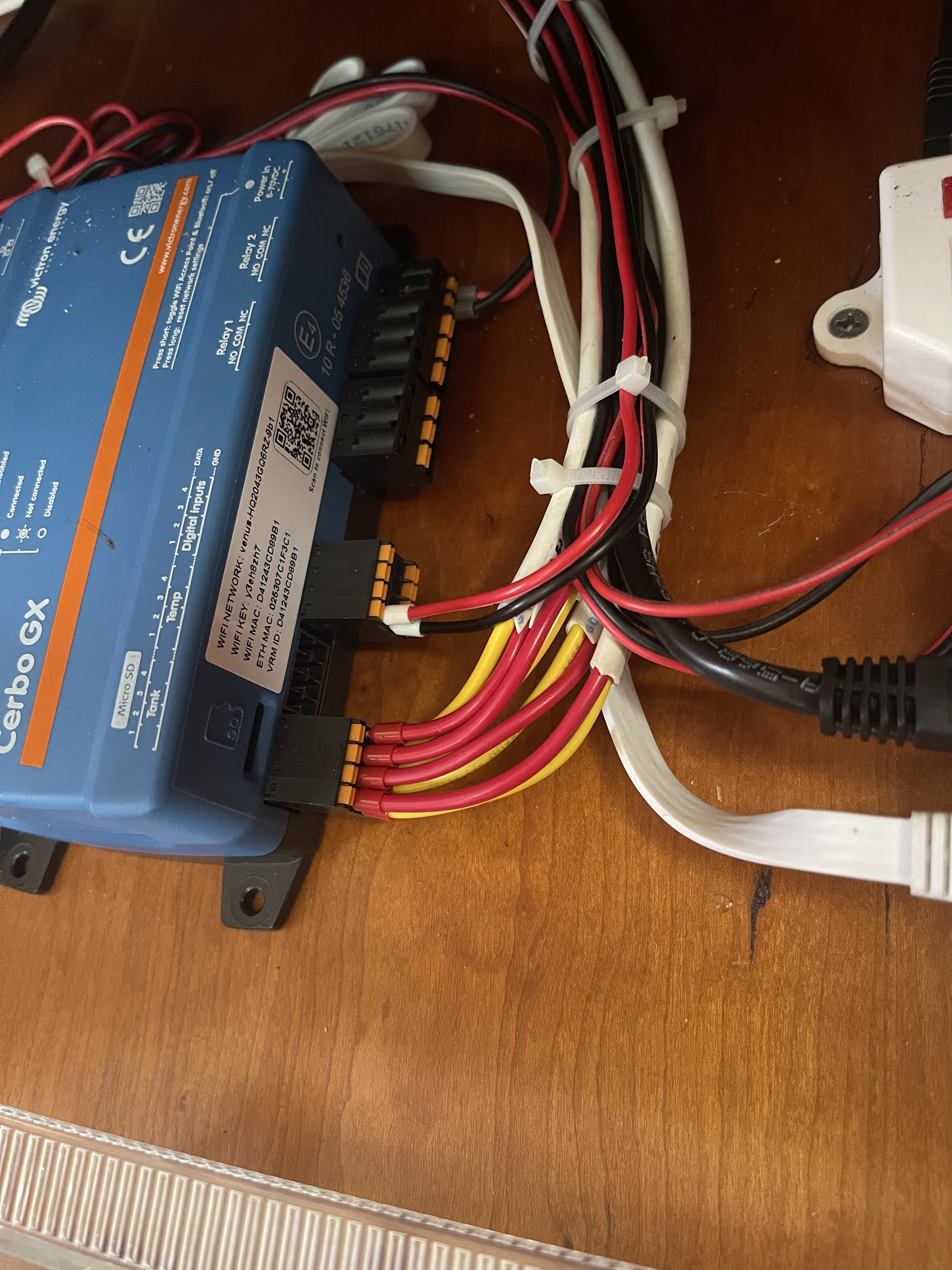
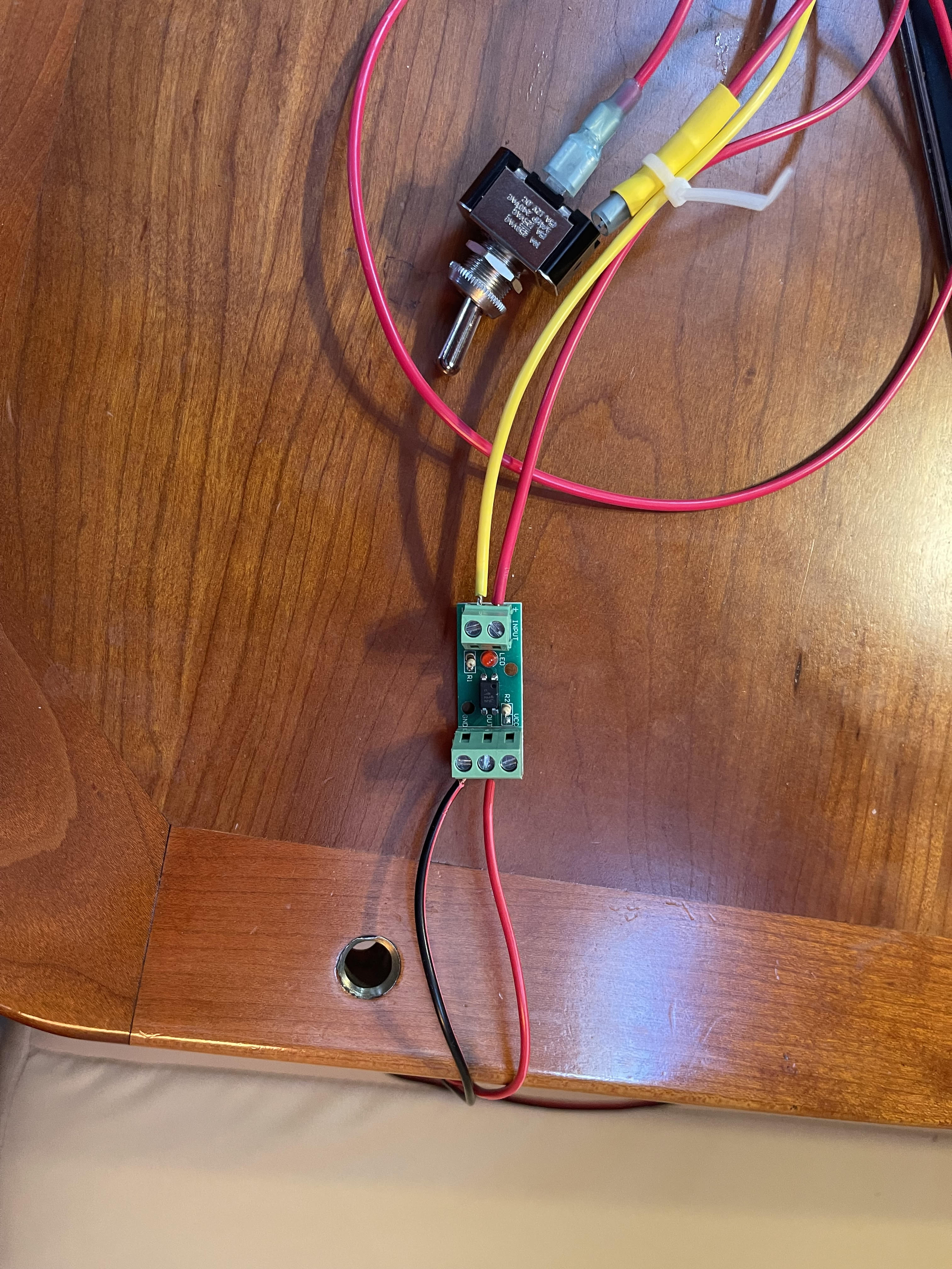
Community, I’ve installed a Cerbo GX. I think I’m happy with the relay functionality. 3v3 octocouple relay to allow power to a 12v fan. The digital inputs are a whole other issue and are doing my head in.
I’ve read the manual and some background stuff but I think I’m not getting it.

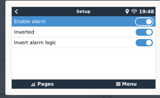
1. Are the inputs powered at 3v3? Do I just need to complete a circuit to change the input state, I.e. short across the digital inputs (I don’t think this is the case but I need to check)?

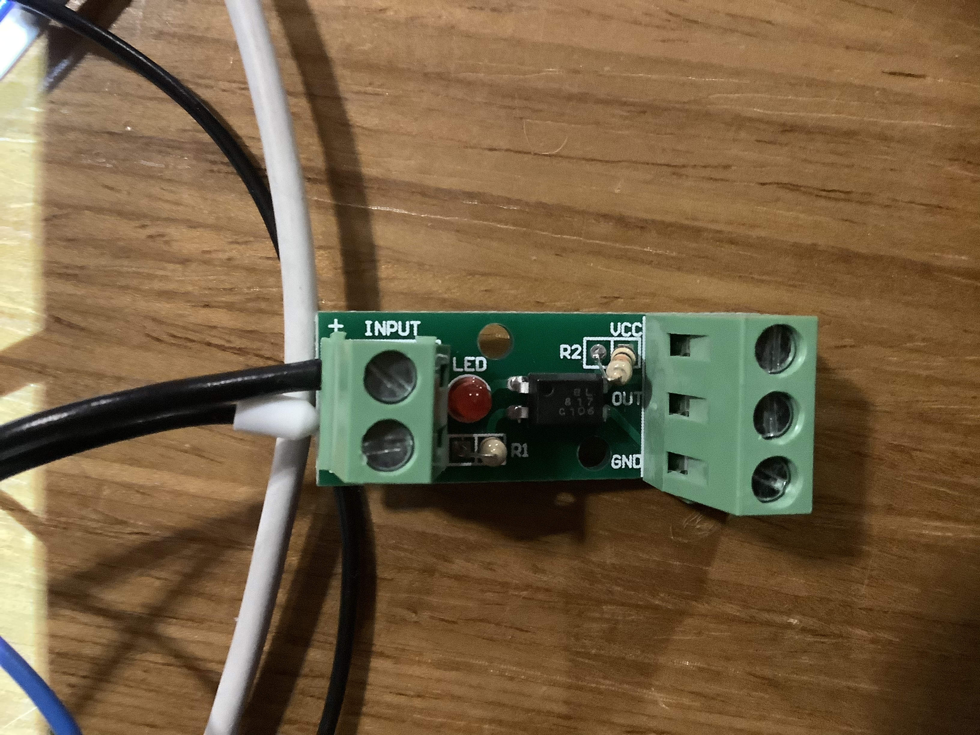
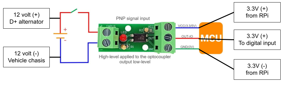
2. So what I‘d like is a digital signal when the bilge pump goes on. Here’s what I think I need to do… Put a relay across the pump power. Have that provide a 3v3 signal to the cerbo digital input. I’m aware that I need a diode or octocouple to protect the cerbo from inductive current/voltage due to the relay coil. The problem is I can’t find such a circuit anywhere.

3. Because I can’t find anything it makes me think I’m way off with my plan. Can you guys suggest a better way of getting an on/off output from the bilge pump?

Thanks in advance,

cerbo gxVenus GX - VGXsensor
2 |3000

Up to 8 attachments (including images) can be used with a maximum of 190.8 MiB each and 286.6 MiB total.

7 Answers
pwfarnell avatar image
pwfarnell answered ·

The inputs are powered and if you have a volt free switch connected between the digital input it will change state when the switch closes, shorting across the digital input. I have a couple of simple float switches connected like this in my bilges to indicate the bilge pumps are not emptying the bilge water.

You may be able to do other things by forcing a voltage on the input ( within limits) but i do not know the details.

I would also like to know when my bilge pump works but i have not solved that because my bilge pumps do not have float switches but inbuilt conductivity probes and I have no easy point to take a voltage signal from.

2 |3000

Up to 8 attachments (including images) can be used with a maximum of 190.8 MiB each and 286.6 MiB total.

jeffryk avatar image
jeffryk answered ·
1 comment
2 |3000

Up to 8 attachments (including images) can be used with a maximum of 190.8 MiB each and 286.6 MiB total.

rupez1 avatar image rupez1 commented ·

This was exactly what I was looking fo. Thanks very much, total legend.

0 Likes 0 ·
randyb128 avatar image
randyb128 answered ·

To answer your exact questions:

1. From the Cerbo GX manual, the inputs are pulled up with a 10k resistor to 3v3 (3.3 volts). Yes, you can just complete a circuit to ground (common) and the input should trigger.

2. If you provide a dry (zero potential) N.O. (normally open) relay contact then you can just run a wire from common through the contact and back to one of the digital inputs of the Cerbo GX.

3. The method jeffryk is suggesting above is the correct way to do this. The solution is inexpensive and no relay is required. The optical isolator provides a noise free input for the processor. Running low voltage processor input wires more than very short distances is never a good idea. The isolator should be as close as feasible to the Cerbo GX. If you need any help wiring up the optoisolator, post on here and I should be able help you out. I did the same for both my bilge pump and a high level water proximity detector.

6 comments
2 |3000

Up to 8 attachments (including images) can be used with a maximum of 190.8 MiB each and 286.6 MiB total.

rupez1 avatar image rupez1 commented ·

Randy, This is vexing me a little. I’ve the noise free switch/ optical transistor/ optocoupler. (See below). I measure 3.2V across the cerbo inputs. I’ve connected 12V across the switch (to simulate a pump running) but I don’t know which of the three transistor terminals to use!!! VCC, OUT, or GND to connect to the cerbo. I’ve also tried just shorting the wire’s from the cerbo but no alarm. What am I missing?

18a6f79a-f89c-415d-9fa4-37f4611e7522.jpeg

0 Likes 0 ·
robert117 avatar image robert117 commented ·

Hello,

Can you elaborate on where to put the neg 5v output wire from the optocoupler? I understand the pos 5v output goes to one of the 4 the digital inputs ports on the cerbo for bilge, highwater, ect signal.

I have a 12v highwater alarm system I would like to integrate into the system. The 12v alarm is connected into the 12v input of the optocoupler, so when the alarm sounds, power is shared to it. I was unsure if connecting neg 5v output from the optocoupler to the negative 12v bus would be okay, or if there is somewhere on the cerbo it should go.

0 Likes 0 ·
jeffryk avatar image jeffryk robert117 commented ·

The negative out from the optocoupler goes into the back of the cerbo. In the attached pic of my Cerbo, the connector with only two red and black wires on it are the digital alarm connector.


img-1130.jpg

1 Like 1 ·
img-1130.jpg (2.0 MiB)
jeffryk avatar image jeffryk robert117 commented ·
I will be down at the boat in a few hours and will see if I can take a pic of how I have it wired up. I think there is a positive and negative coming into the digital side of the cerbo, the output side of the optocoupler, you connect the negative to the ground terminal.
0 Likes 0 ·
robert117 avatar image robert117 jeffryk commented ·
Thank you. Yes I'm looking for the 5v neg port on the cerbo.
0 Likes 0 ·
robert117 avatar image robert117 jeffryk commented ·
Hello,


Any updates? I've been looking at the manual and still haven't found a port for the 5v neg output from the optocoupler. Any guidance for how you hooked up yours would be greatly appreciated.

0 Likes 0 ·
jeffryk avatar image
jeffryk answered ·

I will see if I can find a pic from my test setup, I just left the boat a couple of hours ago and will be likely back in the morning. I have it working by the 12 volts connected to the side with 2 connections in your picture. the other side has the wires going to the cerbo connected to the ground and positive to the "out" port. When 12v is applied the red light on the optocoupler should light up. I did have to switch the digital setup in the cerbo to be inversed in the cerbo device setup.

1 comment
2 |3000

Up to 8 attachments (including images) can be used with a maximum of 190.8 MiB each and 286.6 MiB total.

rupez1 avatar image rupez1 commented ·

Thanks pal. I’ve the red led lit but haven’t reversed any cerbo settings although I’d still have expected it to work but in a reverse sense?

0 Likes 0 ·
jeffryk avatar image
jeffryk answered ·

alarm-setup.png (16.4 KiB)
2 |3000

Up to 8 attachments (including images) can be used with a maximum of 190.8 MiB each and 286.6 MiB total.

jeffryk avatar image
jeffryk answered ·

Rupez1. In there Cerbo, do you have digital input that you are connected to in the Cerbo enabled located at Settings - I/I - Digital Inputs? Does the device show up on your devices pages and show connected? I sent you the setup page last night.

I have attached a pic of my test setup. I put in a simple toggle switch to simulate turning on and off the pump, but it should not matter, once 12v is connected to the other side the Cerbo should see the circuit as "open". My test setup for the wires going to the Cerbo use some extra wire with ferrule connectors that I had from other VE stuff I have bought. As long as the device shows connected in the cerbo then you know you have good connections in the proper ports. See pic attached and I hope this helps. Bilge pump test.jpg


2 |3000

Up to 8 attachments (including images) can be used with a maximum of 190.8 MiB each and 286.6 MiB total.

mike-donahue avatar image
mike-donahue answered ·

Howdy,

This thread seems like exactly where I need to be but I'm not seeing an answer to a situation I have.

Its for a Digital Input on a Venus Pi. I'm trying to trigger a digital input when my vehicle's engine is running. The D+ from the alternator is a 12 volt source and the digital input is 3.3 volt. I've tried two different optocouplers and somehow it allowed 12v to go to the 3.3v line and it fried two RasberryPis. I'm very cautious now! Here is my basic diagram. Am I wiring it wrong or were the past two optocouplers were faulty? Thank you!

untitled-drawing.png


untitled-drawing.png (132.1 KiB)
1 comment
2 |3000

Up to 8 attachments (including images) can be used with a maximum of 190.8 MiB each and 286.6 MiB total.

shawn-willden avatar image shawn-willden commented ·
That looks exactly right, and it should be completely impossible for 12VDC to make it to the 3.3V side. The whole point of an optocoupler is that the only connection between the sides is little light. Inside that IC in the center one side has a small LED and the other an optical sensor, but with no electrical connection between the sides. But it's very odd that you had two bad optocouplers.


I would try again, but this time test it before you connect up the digital input line. Use a voltmeter (or the DC voltage setting of a multimeter) to measure between the ground and out-io screws on the 3.3V side, both with and without the 12V input. You should only see 3.3V on OUT-IO, and only when the engine is running. Once you've confirmed it's working correctly, then hook it up to the RPi.


Also, make sure there's no way current from the 12V side could reach the solder points on the underside of the optocoupler. Maybe that's how the 12V was getting through?

0 Likes 0 ·