question

joanspark avatar image
joanspark asked

just destroyed my VE.Direct to RS232 cable?

What I'm trying to do:
Connecting an RS232-Eth converter (HyFlying Elfin EE10) to a SmartSolar MPPT 100/20 to be able to read out the status via Ethernet. The RS232-Eth converter works as I tested it with 2 terminal sessions and an RS232-USB converter.

Please note that the EE10 only has got RX, TX and GND, no DTR or RTS signals/lines.

What worked:
VE.Direct RS232 cable connected to an RS232-USB converter and then reading the unit with the Victron Connect application on a windows machine (also works with the VE.Direct-USB cable).
This also gives me the data via a terminal window every couple seconds..

What failed and broke my cable..
When I connected the VE.Direct RS232 cable to the EE10 I naturally need to supply the RS232 isolated side with power.. as there are no RTS/DTR lines I used the same power I was powering the EE10 with (same Ground).. 12Vdc and connected it to DTR (pin4 on the VE.Direct RS232 cable) as per the FAQ (https://www.victronenergy.com/live/vedirect_protocol:faq):
"When using an external power supply to power DTR or RTS, the minimum voltage is 5V, and maximum is 12V. Note that it is normally not necessary to use an external power supply for this: normal serial ports will either automatically drive DTR or RTS high. And if not that, than you can control those pins to be high from within the software."

The VE.Direct RS232 cable stopped working after that.
I'm currently re-engineering the circuitry on that board that is in the DB9 connector housing as several of the tiny diodes must have failed and seem to have burned through. Further, there doesn't seem to be any voltage converter in there, which means both the ADuM1201AZR and LM555CM SOIC-8 chips must have dealt with the 12Vdc - ouch. The ADuM1201AZR per datasheet is only capable of 7Vdc absolute maximum. So I'm pretty confident that I shot this chip on the RS232 side. The TTL side (MPPT charger) didn't get harmed luckily.

The circuitry in that cable doesn't make sense to an electronics engineer that I asked for help in identifying what went wrong. Per his opinion the version I got was lucky to have worked at all as the wiring in there is just plain odd/incomplete/unusual.

The pcb has this code on it: VE / REV-1 / 6-08 / 08204

I have another VE.Direct RS232 cable on order that should arrive with me in about 14 days or so (FNQ, Australia) which I will have inspected before I do anything with it. I also ordered some isolating RS232-TTL conversion connectors from Aliexpress which will take over a month to reach me.. they use a similar isolation chip but use a different powering regime and take a common rs232-TTL level shifter circuit.

https://www.aliexpress.com/item/32846014060.html

So what do I do now about the broken VE.Direct cable I got here (or the parts of it).
Do I get a replacement? Not sure I'd want one though, by how it's built on the inside. For what I need it it's probably useless unless I stay with powering it below 6Vdc or so.. and even then I'm not convinced of it being designed properly.

:-(

VE.Directwiringethernet
2 |3000

Up to 8 attachments (including images) can be used with a maximum of 190.8 MiB each and 286.6 MiB total.

2 Answers
joanspark avatar image
joanspark answered ·

victron-vedirect-rs232-cable-pcb.jpg
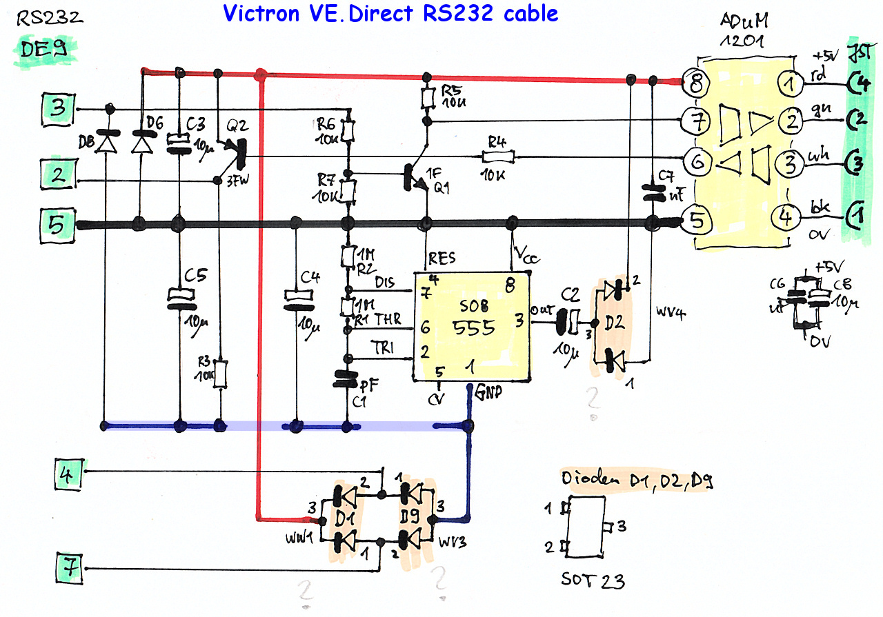
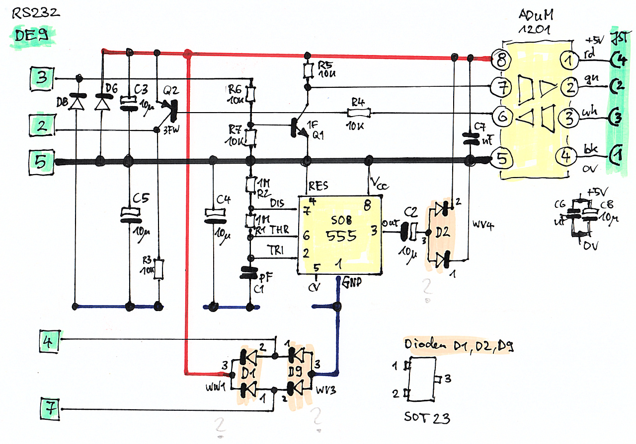
This is the circuitry of the pcb that's in the DB9 housing (99% confident).
It's a 4 layer pcb (not needed IMHO) and some connections have been hard to trace (vias under pads are a big no-no in the industry for example, but have been employed here). The orientation of the diodes is guesswork, due to the unit I have here being damaged. How they are depicted is most likely going to work to create the power for the ADuM and the RS232 voltages from the DTR/RTS pins of the DB9 connector (not convinced this is a good/proper design - comment by the EE that helped me), but it's not working from +5-12Vdc then. It would need -12Vdc to run per the logic.. anyhow, I'll get back to this once I get a new cable and can look at it with an oscilloscope while still in working order.

For deploying this in the field it's just not properly engineered enough though (things like the isolation that is being created by the ADuM is being screwed up by too close traces/vias somewhere else on the board), I'll have to look elsewhere for a solution I can trust to run reliably.


2 comments
2 |3000

Up to 8 attachments (including images) can be used with a maximum of 190.8 MiB each and 286.6 MiB total.

johnny-brusevold avatar image johnny-brusevold commented ·


@JoanSpark

Have used the converter from Duppa for a while, and it works very well

Duppa

Video

0 Likes 0 ·
joanspark avatar image joanspark johnny-brusevold commented ·
USB <> RS232 is useless to me.. I need Ethernet <> RS232 and the galvanic isolation capabilities of the VE.Direct cable.

Thx for the comment.


0 Likes 0 ·
joanspark avatar image
joanspark answered ·

Did some more testing and then discussing with the EE.

The original plan of the whole circuit seems to have been to run the ADuM from the TX pin of the computer alone. Changing TX (RS232) from logic 0 (+??V) to logic 1 (-??V) would via D8 draw capacitor C5 down to store the negative level for Q2 that the RX of the VE.Direct signal needs to be recognized by the computer (couple times back and forth and it's possible to drive something with this).
From that very same negative level the LM555CM was supposed to make the positive voltage to drive the ADuM and also Q1 so the VE.Direct device can recognize the computer signals (change settings on the VE.Direct device).

victron-vedirect-rs232-cable-pcb-circuit-mod.jpg

But the LM555CM seems to have been too power-hungry for this and they cut the wiring and instead got the positive power from the DTR pin of the RS232 interface. This is done by the Victron Connect App upon starting (or anytime the 'refresh' button is hit).. it does take control of any COM port available on the machine and it sets pin 4 (DTR) to +??V (logic 0).
So now they got a source for powering the ADuM and funnily enough the LM555CM is not needed anymore, which is prob why this circuit didn't make sense, as it wasn't doing anything purposeful due to the missing connection between it's pin 1 and C1 and R3 (see image above, light blue line). No idea why it's being populated still..

The only thing that definitely is wrong is the VE.Direct FAQ and it's suggestion to be able to supply 12V on the DTR and/or RTS pins from a normal power source. The diode D6 and then further the ADuM are incapable of dealing with this.
You should not supply more than 6V to either DTR and/or RTS if you want to keep your cable functioning.
That a RS232 interface with it's +/-15V works is due to D6 being able to suck up some heat as the source is high ohmic and not a lot of current comes out of it.
But any other power source with more than 6V will overwhelm D6 and then kill the ADuM chip.

PS: also found a drawing mishap, D2 the diode from 1-3 was wrong in the older drawing.

PPS: we're designing our own level shifter/isolator circuit now. It will be driven by +12V (as the Ethernet<>RS232 converter needs a power supply anyway). If there is interest I can drop the ecad files once ready here or on one of the git places.

This is the pcb board from which above circuit is from..

victron-vedirect-rs232-cable-pcb-photo.jpg


2 |3000

Up to 8 attachments (including images) can be used with a maximum of 190.8 MiB each and 286.6 MiB total.

Related Resources

VE.Direct protocol FAQ

Additional resources still need to be added for this topic