I have a multiplus II and I have a n electric boiler hanging on the AC2 output. So when my batteries are full. The assistant switches on the AC2 output and heats the boiler. Is there a possibility to manually switch the AC2 out. A switch on the VRM would even be nicer.
asked
switching AC2 on the VRM
The only way that I can think of is to have 2 switch conditions in the programmable relay assistant, 'SOC' (I assume that is your current switch condition) and 'Input signal', then wire the selected Aux input to one of the relays in your GX device.
You can switch the relay via remote console and if either of the 2 conditions are satisfied AC2 should be active.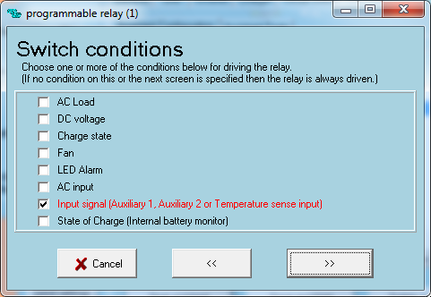
@Mark
Where in the remote console, you can switch the relays manually?
Harold
Hi Harold, just under Settings > Relay.
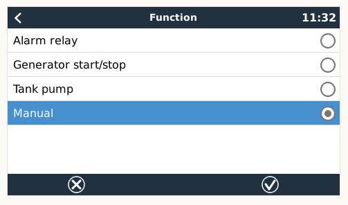
If you want to control Relay 1 manually you also need to set the function to manual control.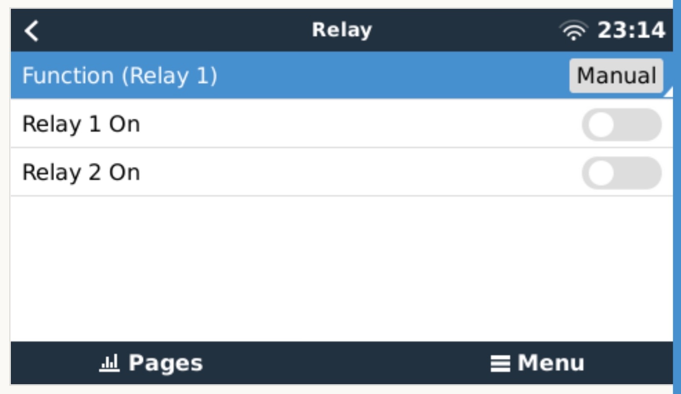
I think this is on a Cerbo?
It will not switch the relays in the Quattro or Multi!
Hi Harold, yes that is the GX device (CerboGX, VenusGX, CCGX,etc.) user interface, accessed via remote console.
Please read my answer above about the workaround I proposed to switch AC2 relay on the VE.Bus device (MultiPlus or Quattro) from the GX device.
You will need to physically wire the GX device relay into one of the Aux input of the MultiPlus/Quattro and set up some programmable relay assistants (https://www.victronenergy.com/live/assistants:overview_of_available_assistants) to monitor the state of the Aux input (open or closed circuit) and switch AC2 relay on and off.
Hi Harold,
That is incorrect, yes you can manually control the single relay on a CCGX.
Please read my comment above to you - "If you want to control relay 1 manually you also need to set the function to manual control".
I also just connected up a CCGX and tested this to re-confirm - it works correctly.

So there is no way that this is possible to adress to a switch in the VRM like I start/stop my generator from distance?
thx Mark, I'll get that tested.
here is a option - but you still have to use the remote console option - if you have a cerbo and or you dont use relay 1 on the ccgx for anything. you can use this relay to turn say aux1 closed or open and thus control AC2 out.
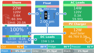
download and install for Kevin Windrem GuiMods as this then adds this feature and many other nice screen updates as well ( these can be turned on or off by selection)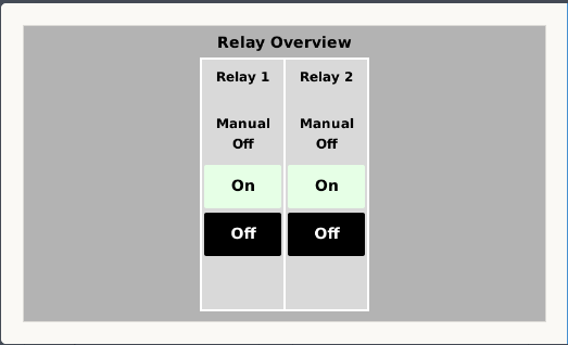 screen shot sample as below
Below is some more detail describing how to setup the assistants required to switch AC2 based on the status (open or closed circuit) of an Aux input.
Disclaimer: Configuration of a VE.Bus device should be completed by a trained/experienced Victron installer or dealer - do at your own risk, if you are not confident engage an installer to help.
1- Download and install VE.Configure 3 from the software download page https://www.victronenergy.com.au/support-and-downloads/software
2- Connect a VE.Bus to USB interface to the VE.Bus device (MultiPlus/Quattro) and a PC https://www.victronenergy.com/accessories/interface-mk3-usb
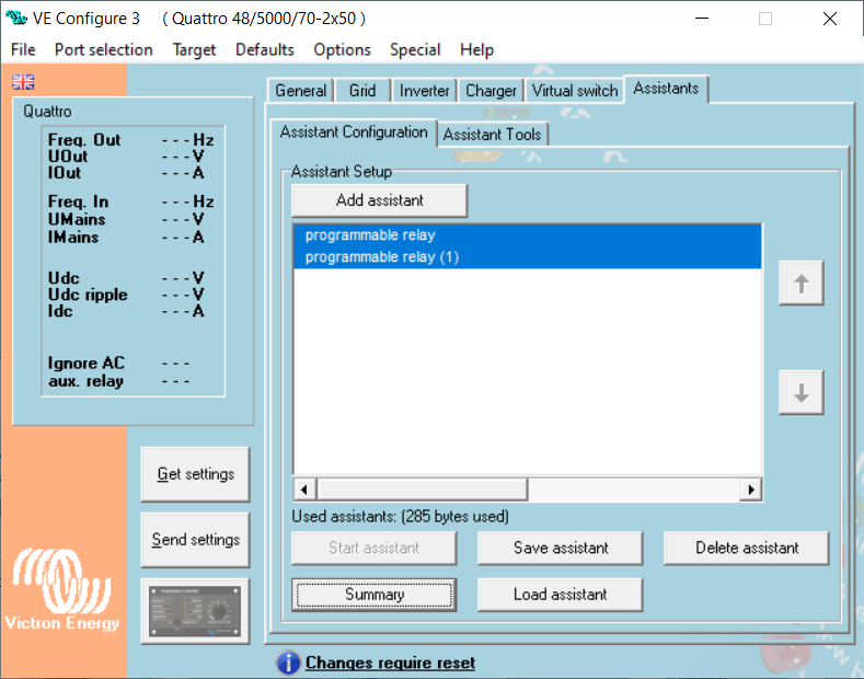
3- Open VE Configure and connect to the VE.Bus device
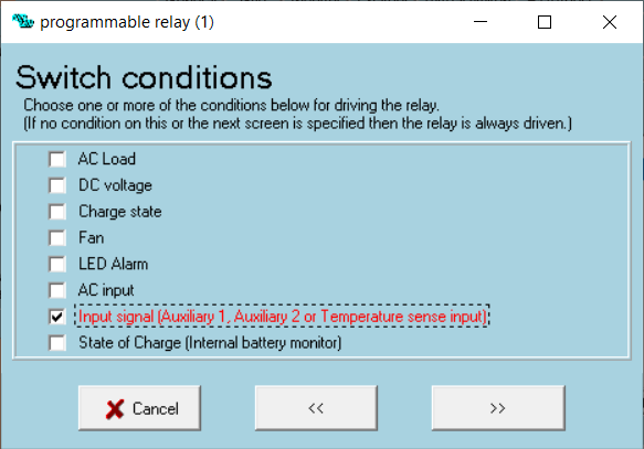
4- Select the the Assistants tab and load up 2x programmable relay assistants (you may need to disable the 'Virtual switch' first if there is a condition active)
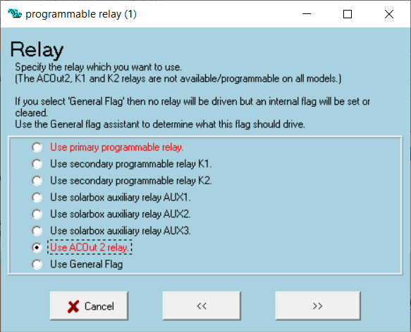
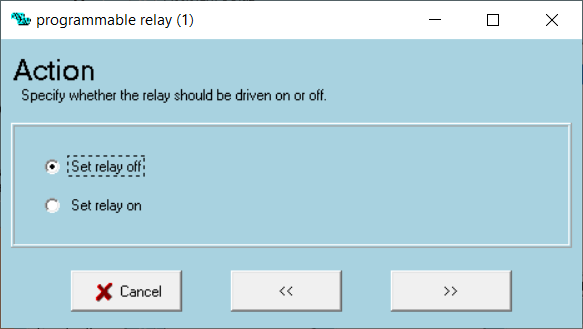
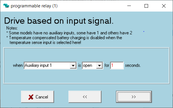
5- Configure the first programmable relay assistant to turn AC2 relay on - for example
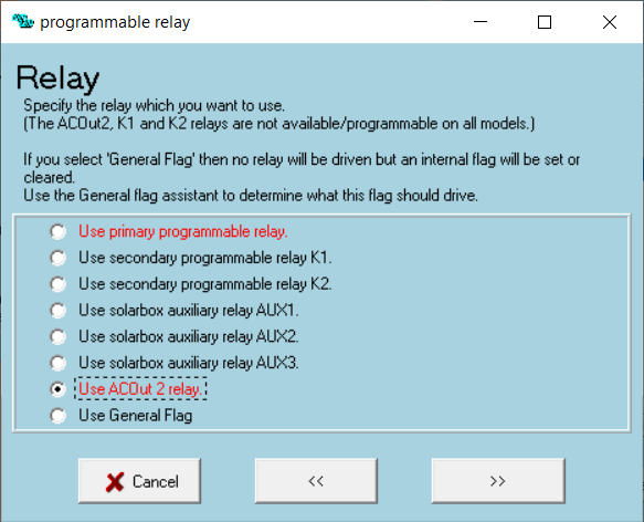
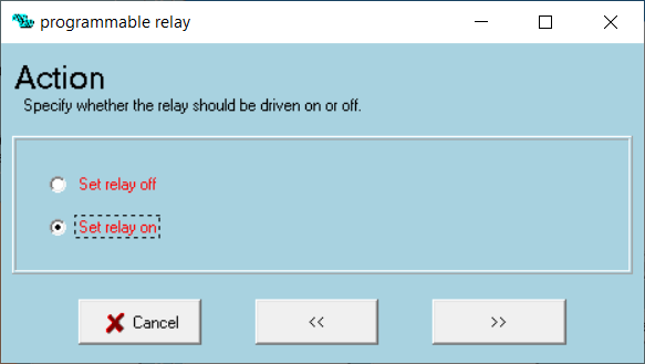

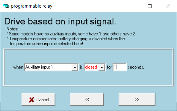
6- Configure the second programmable relay assistant to turn AC2 relay off - for example
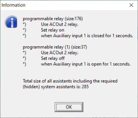
7- Highlight all assistants and check the logic in the 'Summary' window
So Mark, you still have to wire the AUX1 with the gerbo relay? Cause I don't understand if this is still necesary
Yes, you need to physically wire one of the GX device relays to one of the MultiPlus/Quattro Aux inputs; you can use any relay on the GX device and any MultiPlus/Quattro Aux input, just set up the assistants to suit.
The GX device relay is what will open or close the Aux input - that is the workaround. If you only want to control AC2 locally/on site you could use a simple switch instead.
Thank you so much for adding the Relay switches to the VRM portal. This is such a good add on.
Victron rules