question

magicmike avatar image
magicmike asked

DIY: Cerbo and Generator with Engine Start Stop Push Button (12v) *** Wiring for Dummies ***

Hello,

After few days i found out solution and i have tested this 'system' to start generator with impuls.

For me its working like a harm but im more than happy to hear from people more experienced than me.

It ll be handy for you if you have generator with push start button (standard car 12v engine start button).

It took me a while to get it sorted in head and i had done few tests + i got some help from outside ofc. *thx reddit with realys trick*.

Once you have this button:

img-20211015-162247.jpg

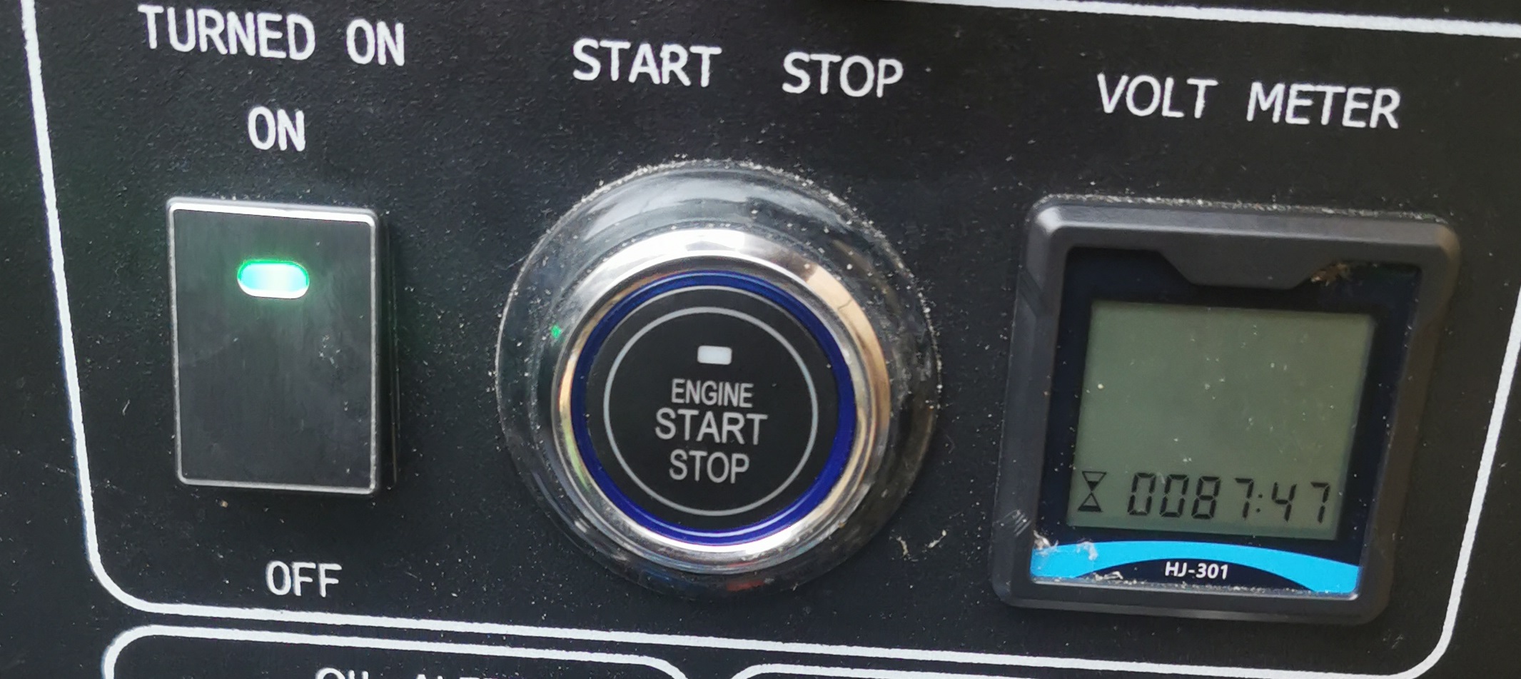
Im almost sure that you got build in 12v battery in your generator.


You can find this button in most of Chinese or branded generators that came of 'my friends'. Most of buttons works same way if not all... :)


Why you might need this?


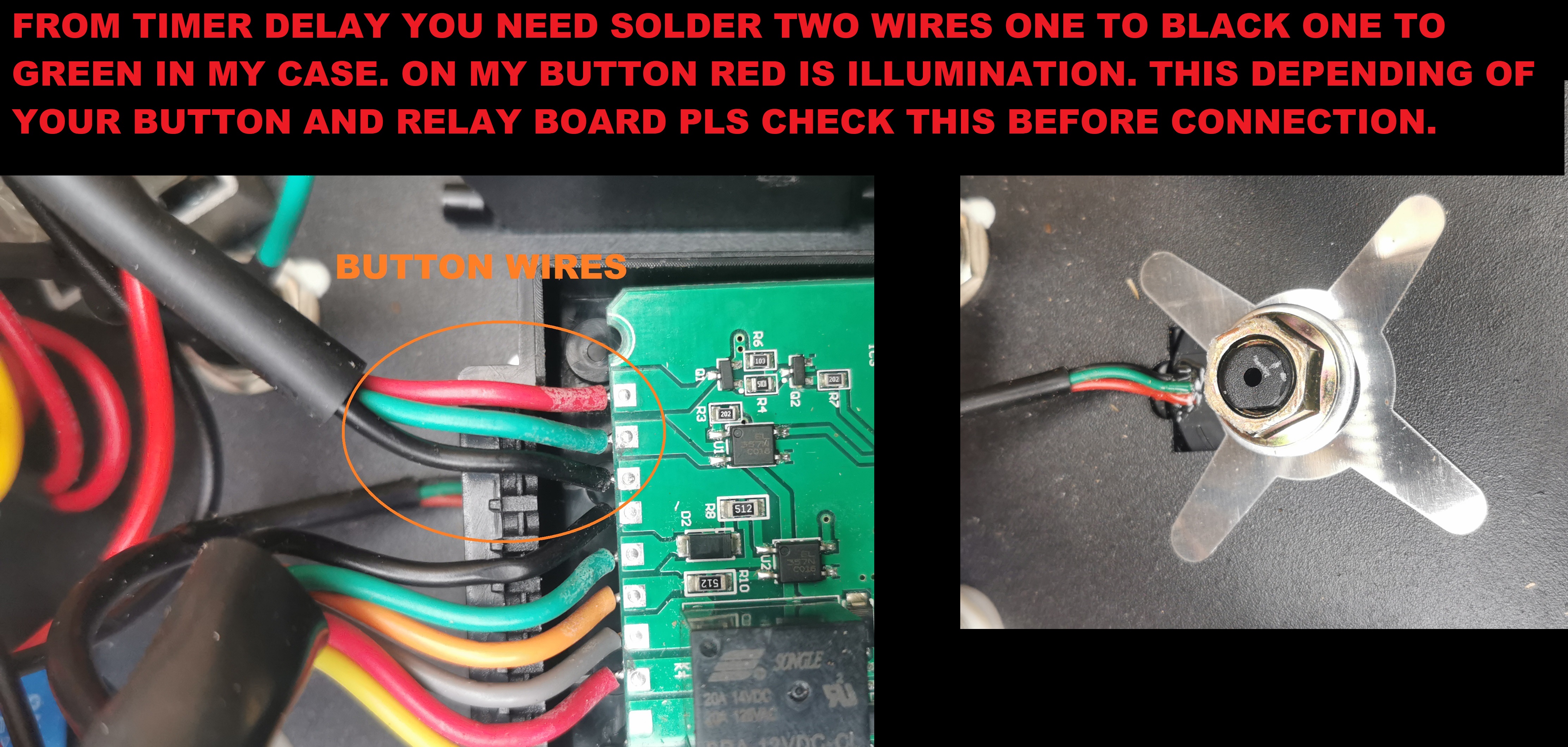
To activate start and stop system you need to join two wires together with is 'Plus and Minus'

Start and Stop buttons has 3 wires- Plus, Minus and Illumination.

Because relay in CERBO is 'ON/OFF'. It gives constant output on COM wire.

Ok that's no problem when you wants to start generator but what if you start generator remotely and how would you turn it off?

*You can hit 'turn off' on CERBO that means you ll only loose power on COM wire- that's not way.

Then you have to hit 'turn on' to trigger wires and then AGAIN to turn it off.

Cerbo cannot be programmed to send just a signal on COM wire. Relay is constant open or closed. BAD/ WRONG/ SAD.


My tutorial ll costs you probably 30mins to 1hr of work depending of your skills and 10euro, depending how tidy you need it done etc.

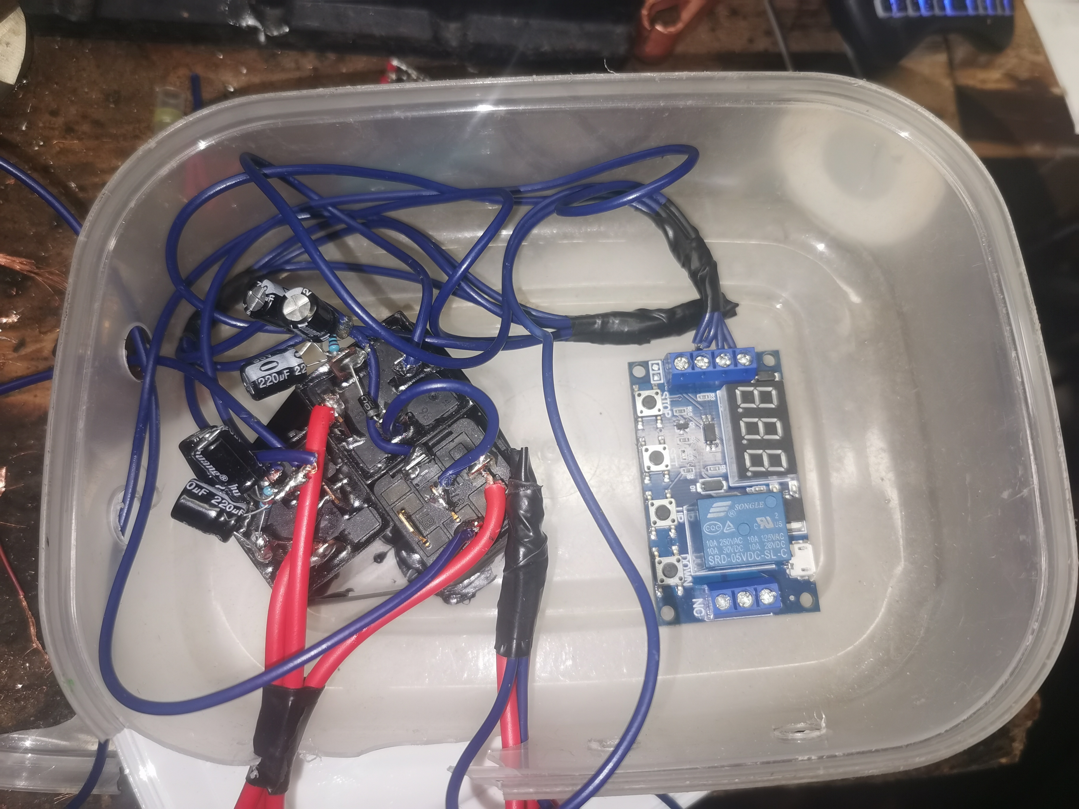
On pics below that i attached i ll show you my 'test' modules that needs to be redone and need some 3d printed case to get it nice and tidy.


What we need;

*Bit of cable.

*3-4 fuses 10A + fuse holders.

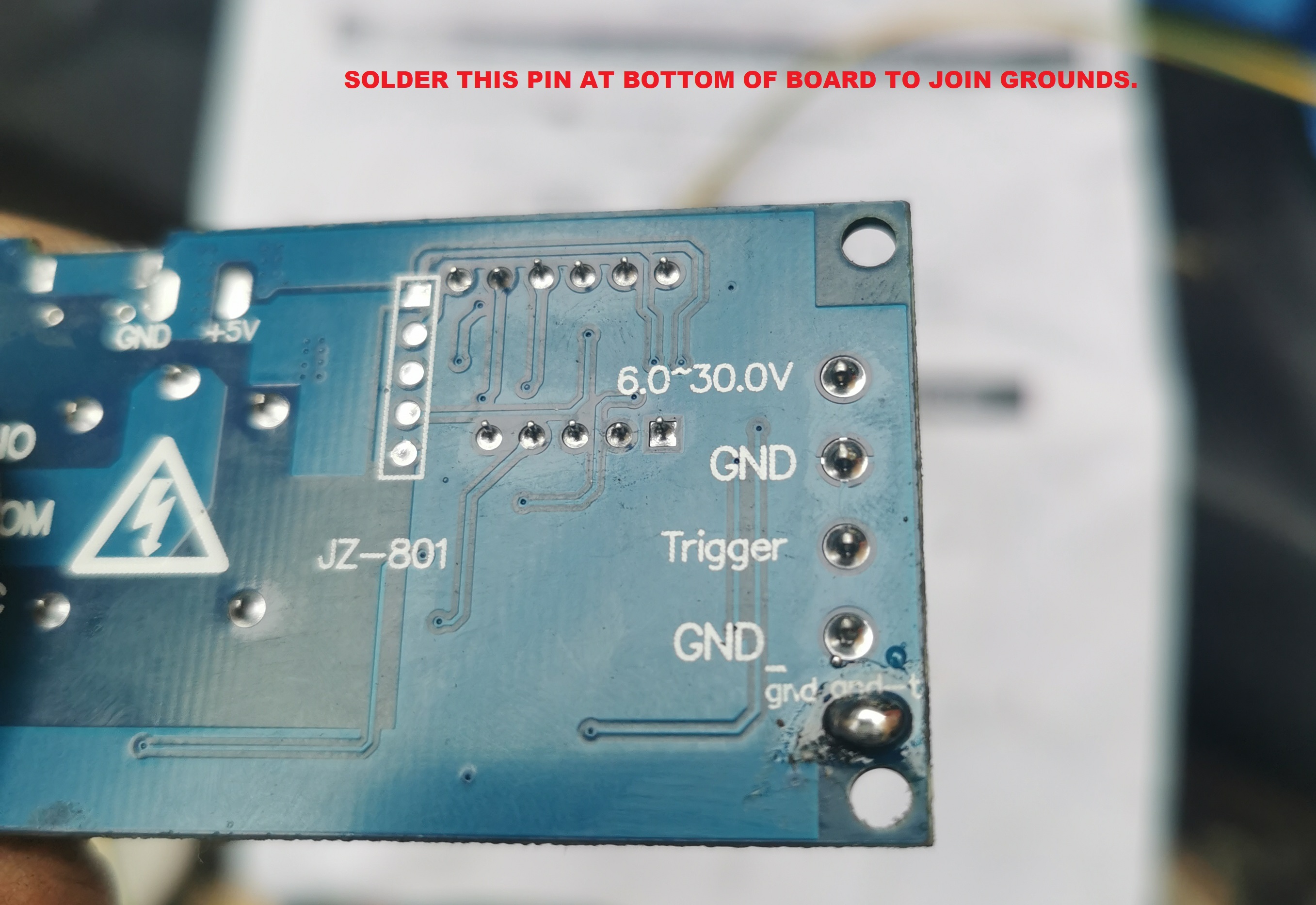
*Trigger Delay Timer- model JZ-801 (can be got on ali for 3 euro or amazon for 10.)
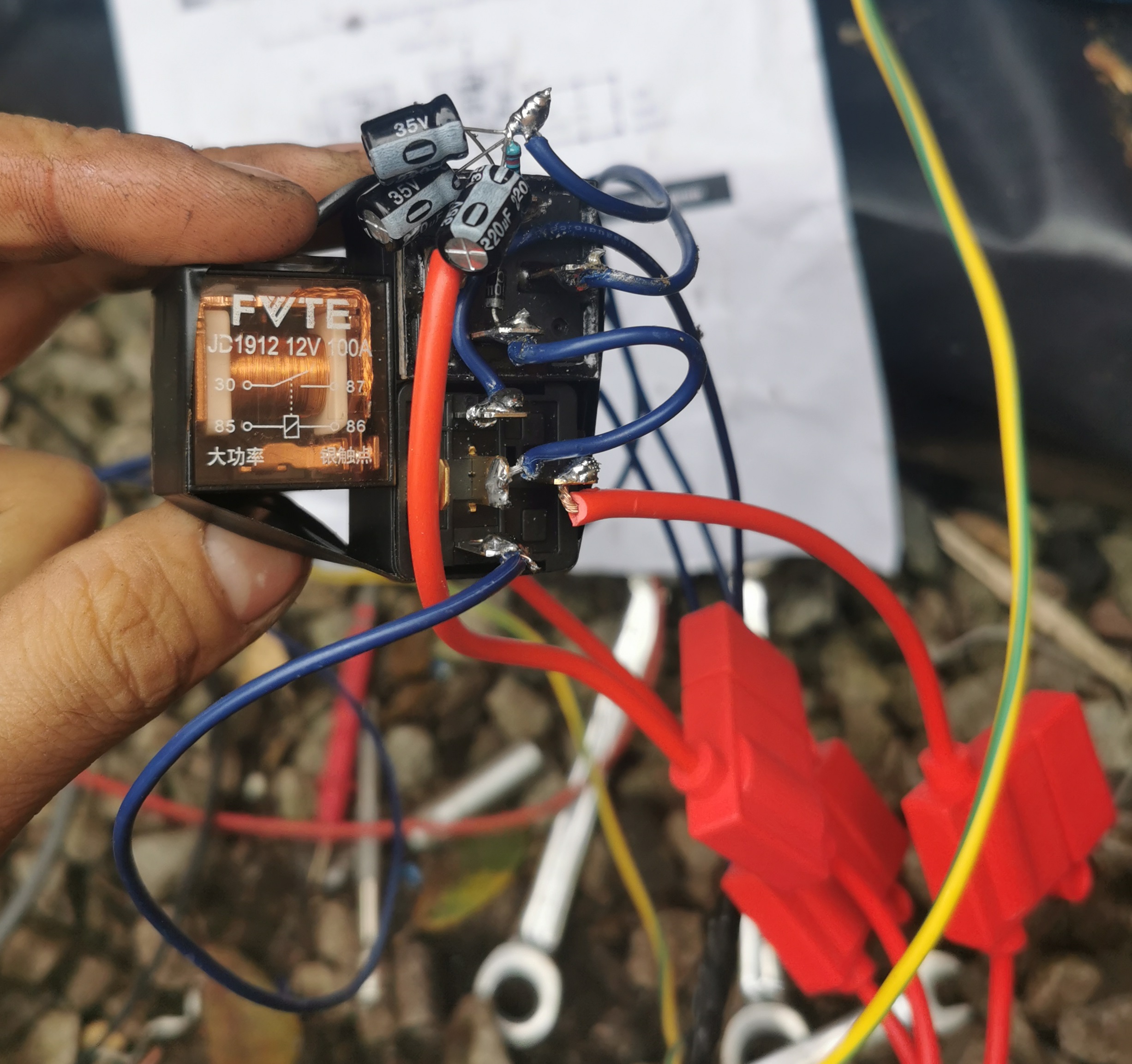
*2x 4 pin 12v relay

*1x 5 pin 12v relay)

*Wire terminals

*Soldering Iron

*6x 220uf Capacitors

*2x 10 Resistor

*x 1N4007 Diode

On diagram below (thanks the12volt.com) I show how i have everything connected. Instead of 1kUf resistor i used 3x 220uf.

screenshot-2021-10-14-023134.png


*** TRIGGER DELAY TIMER RUNS ON PROGRAM 4 AND SET FOR 1 SEC. ***

img-20211015-162211.jpg


img-20211015-180129.jpg

img-20211015-162217-1.jpg

img-20211015-162235.jpg

Here some quick notes from the12volt.com;

Constant to Momentary Output - Positive Input/Positive Output Relay Wiring Diagram

The capacitor allows the coil of the relay to be energized until the capacitor stores a charge, thus de-energizing the coil. The resistor bleeds off the charge of the capacitor when positive voltage is removed from the other side of the coil. You can increase the output time by simply changing the value of the capacitor. This one will give you about a 1/2 second output.

Momentary Positive Output when Positive Switch Turned Off Relay Wiring Diagram

When the switch is turned off, the coil of the first relay is de-energized closing the normally closed contacts and sends 12V (+) to the coil of the second relay. The capacitor allows the coil of the second relay to be energized until the capacitor stores a charge, thus de-energizing the coil. The resistor discharges the capacitor when positive voltage is removed from the other side of the coil when the switch connected to the first relay is turned back on. You can increase the output time by simply changing the value of the capacitor. This one will give you about a 1/2 second output.


cerbo gxGeneratorwiringwiring diagram
2 |3000

Up to 8 attachments (including images) can be used with a maximum of 190.8 MiB each and 286.6 MiB total.

3 Answers
cleaver avatar image
cleaver answered ·

I use 2 DEI car alarm timed relays (pulsed). one to activate on energize and one to activate on de-energize. These relays can be adjusted for pulse legnth. Which works perfect for most push button generators.

However my new Cummins P4500i has a DTDP switch for main power. so I had to run wire to run 2 micro relays that I installed in the generator. One is set to NO. other to NC. the NC is installed in the generator kill circuit. and the NO is installed for power. This allows me to have the Cerbo set to auto-start and stop the generator.

Because the generator will be used for other things than just powering my RV. I need to have the factory switch still available to use..

2 |3000

Up to 8 attachments (including images) can be used with a maximum of 190.8 MiB each and 286.6 MiB total.

magicmike avatar image
magicmike answered ·

My switch is still available to use any time same same as remote control. I soldered wires to wires that goes to button, no need to cut.

My push button is more less same as yours I believe with 433hz remote control

2 |3000

Up to 8 attachments (including images) can be used with a maximum of 190.8 MiB each and 286.6 MiB total.

Nicholas Herbst avatar image
Nicholas Herbst answered ·

I am trying to implement something similar now, but there is a far simpler way to create a momentary output from one of the Cerbo relays now with Venus OS Large image supporting Node Red.

I have create a flow which creates a momentary (pulse) output on relay 2, linked to relay 1 which is configured to run the standard gen start/stop control conditions.

I am still trying to understand the operation of the gen start/stop 12V button as my unit has 5 wires.


2 comments
2 |3000

Up to 8 attachments (including images) can be used with a maximum of 190.8 MiB each and 286.6 MiB total.

derrick thomas avatar image derrick thomas commented ·

Your standard momentary start/stop generator switch (as found in most mobile applications ie. RV or marine) usually has 3 poles for the "switching" and 1 or 2 poles for the run indicator led, and sometimes hour meter. The switch usually controls a ground signal. When depressing either start or stop position the ground circuit is completed signalling the auto controller to do that function. There are a few auto controllers that use positive control circuits instead of ground. Make sure you know which one you have or you may damage the controller.

0 Likes 0 ·
zlinhart avatar image zlinhart commented ·
Did you ever figure this out with the 5 wire button? My new Genmax 3500 duel fuel has 5 wires going to the Start/Stop button and would like to be able to auto start it with my GX.


It also has a remote control which I pay just use as it seems simpler to wire.

0 Likes 0 ·