question

motylu avatar image
motylu asked

Multiplus-II grid protections and feed-in control in 3-phase configuration

Hello guys,

I am from Czech Republic and planning to use 3x MultiPlus-II 48/3000 in 3-phase configuration and DC coupled system with PV array (2 strings, 2 MPPTs) and Pylontech batteries.

Of course I will set grid code to "Europe (EN50549-1:2019)" and there are several options for over/undervoltage and over/underfrequency protections, conditions for normal connect and reconnect after trip, controlling power according to frequency and voltage and also option for use Aux 1 input as feed-in disable signal. Setting of all protection is clear for me but our electric distributor have several requirements for connecting "micro-generators" (PVE with P < 10 kW) to the grid, so I have two questions about grid code functionalities especially in 3-phase mode:

  1. If the condition for activating grid protection on one Multi is met and therefore AC input of Multi must be disconnected from the grid, is then automatically disconnected all Multis from the grid?
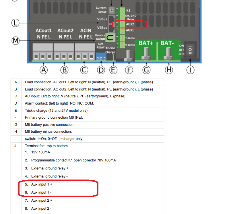
  2. I want to use disable feed-in using Aux 1, because our distributor must be able to reduce power feeding to grid (for these micro-generator only two states: 100% and 0% feed-in). My question is how disable feed-in function is realized in practise on Multis and whether I must used Aux 1 on all Multis (for example with 3-pole relay, each pole for each Aux 1) or if is sufficient to use Aux 1 only on one Multi (probably on phase L1) and feed-in will be automatically disabled in general for all Multis?


Thank you very much for your answers.

Multiplus-IIgrid3 phase
2 |3000

Up to 8 attachments (including images) can be used with a maximum of 190.8 MiB each and 286.6 MiB total.

8 Answers
Matthias Lange - DE avatar image
Matthias Lange - DE answered ·

1. All will disconnect from the grid.

2. The signal is only needed at the master (L1).

1 comment
2 |3000

Up to 8 attachments (including images) can be used with a maximum of 190.8 MiB each and 286.6 MiB total.

motylu avatar image motylu commented ·

Thank you very much for your quick response. Function is as I expected, so it will be easy to implement!

0 Likes 0 ·
motylu avatar image
motylu answered ·

How to set up all Multis in this configuration with control relay connected only to Aux 1 of master (L1) Multi?

I will add ESS assistant to all Multis, change grid code on all Multis and what about setting of Aux 1? Set Aux 1 for disable feed-in on all Multis together with connection only Aux 1 of master Multi? Or set it only on master Multi?

And is it possible to connect Aux 1 on all Multis to one 3 pole relay, set disable feed-in on all Multis - as backup, if there is a problem for example with one pole contact of relay or Aux 1 input of master Multi?

3 comments
2 |3000

Up to 8 attachments (including images) can be used with a maximum of 190.8 MiB each and 286.6 MiB total.

shaneyake avatar image shaneyake commented ·

With the correct Grid code applied, AUX 1 will trigger the the system to stop exporting.
You can just put the same settings on all units but you only need to trigger the AUX 1 input of the master. It will disable feed-in on all mults if master is triggered.

0 Likes 0 ·
motylu avatar image motylu shaneyake commented ·

Many thanks for your answer.

So this means that trigger AUX 1 of master Multi will disable feed-in on all Multis, it is definitely clear.
But what about trigger AUX 1 on slave Multis? This will not disable feed-in anyway? I am thinking this way only for redundancy control as backup in case of problem with AUX 1 on master Multi, because I have spare 4 pole relay…

0 Likes 0 ·
shaneyake avatar image shaneyake motylu commented ·
I am not sure, probably ignored. I however wouldn't do it as this isn't' the intended install method and you might get some unintended results.
0 Likes 0 ·
moon avatar image
moon answered ·

Hy, I am new in the forum. Since I am facing the same problem.....

3x MultiPlus-II 48/3000 in 3-phase configuration and DC coupled system with Pylontech batteries. Grid code Germany VDE-AR-N 4105...., internal NS protection.

If I bridge the AUX 1 of master (L1) Multi (or just short circuit with a potential free relais) in my opinion the feed- in into the grid should stop. But it continues with a little lower power to feed into the grid. I have absolutely no idea why. Is there someone with a clue why?

Thanks for your help!

2 |3000

Up to 8 attachments (including images) can be used with a maximum of 190.8 MiB each and 286.6 MiB total.

motylu avatar image
motylu answered ·

Hi again.

I had already done the installation without PV modules in February, then in April I added PV modules and completed the installation. So I have 3x MultiPlus-II (in 3 phase configuration, FW v490), 2x MPPT (150/60 + 150/70), Cerbo GX and 3x Pylontech US3000C. Grid code set to Europe (EN50549-1:2019), grid code settings according to requirements of our distributor and in all Multis is set Aux 1 for disable feed-in.

If I activate Aux 1 by one pole relay in master (L1) Multi, feed-in on L1 Multi is disabled (it seems, that the Multi is then limited as charger, inverter is disabled), but on other Multis (L2 and L3) feed-in is not disabled as @Matthias Lange - DE wrote...!

So my question is, because this function is not desribed anywhere in the documentation, how I must make wiring and make configuration of Multis? Is it necessarry to activate Aux 1 on all Multis (by 3 pole relay), is it necessary to configure Aux 1 to disable feed-in only on master Multi, or... ?!

Another question is why inverter function of Multi is disabled after activation of Aux 1, because if I deactivate option for DC-coupled PV feed-in in Cerbo GX menu, everything works perfectly even with inverter function still in work.

Because in the Czech republic energy consumption is not calculated as sum of all phases, but it is based on power in individual phases, I have set Multiphase regulation method to Individual phase. Even if I have this setting, calculation of grid power and also energy from/to grid (in Remote Console and VRM) is calculated in wrong way, because it is still calculated as sum of all phases! Is it possible to repair this bug?

Thank you very much for answers.

2 |3000

Up to 8 attachments (including images) can be used with a maximum of 190.8 MiB each and 286.6 MiB total.

motylu avatar image
motylu answered ·

Hi again,

because no one seems to have time for help us with this incorrect behaviour with otherwise great products, I have done some testing myself.

Today I changed grid code settings on second (L2) and third (L3) Multis - simply unchecked option for disable feed-in based on Aux 1. Then I activated Aux 1 on the first (L1) Multi, but result was the same as before - only on L1 Multi was disabled feed-in (inverter function was disabled on this first Multi respectively).

So my question is, can someone from Victron describe in detail function of Aux 1 in 3 phase configuration when disable feed-in based on Aux 1 in the grid code settings is enabled? And why the inverter function of the Multi is disabled in this case, because then you are not able to get power from battery or PV and you can only consumed energy from grid - requirement by distributor and also EN50549-1 is that feeded energy to grid must be set from P4 (100%) to P0 (0%), but nothing about deactivation DC to AC conversion...

Thanks for help.

2 |3000

Up to 8 attachments (including images) can be used with a maximum of 190.8 MiB each and 286.6 MiB total.

smejfi avatar image
smejfi answered ·

Hi, Im from Czech Republic as well and just want to confirm that function "Use Aux1 as disable feed in signal" doesnt work properly. I would expect that activating this function on master L1 unit would just uncheck "feed in enabled" in ESS settings in VRM, but what it actually does is exactly what @motylu says and that is it only turns of inverting and only on that specific unit where aux1 is activated. I would really expect some reaction from Victron here. Thank you in advance @Johannes Boonstra (Victron Energy Staff), @Daniël Boekel (Victron Energy Staff) or someone else.

2 |3000

Up to 8 attachments (including images) can be used with a maximum of 190.8 MiB each and 286.6 MiB total.

motylu avatar image
motylu answered ·

Hi,

because nobody can help us obviously, we have to deal with it ourselves.

I solved this problem with simple flow in Node-RED and digital input of Cerbo GX with large Venus OS. I simply use digital input, which is controlled by SPST relay (coil of this relay will be controlled by distributor using "HDO"), and based on input value I switch on/off feed-in option in "ESS System Setting" node, so result is the same as if I switch on/off "DC-coupled PV - feed-in excess" option under ESS setting in Remote console.

6 comments
2 |3000

Up to 8 attachments (including images) can be used with a maximum of 190.8 MiB each and 286.6 MiB total.

dalibor-farny avatar image dalibor-farny commented ·
Hi! I am in the same situation as you (czech), building solar plant with almost the same HW setup. A couple of thoughts:

1. Why do you mind the multi is switching off inverter when distributor shuts down your system via HDO? Practically, this will never happen or will happen rarely. I would prefer my system to cleanly respect the laws/standards and not bother my system is taking electricity from the grid in the rare situation when distributor needs to shut it down.

2. I think the PV system needs to be galvanically isolated after receiveing P0% signal via HDO from the distributor. IMHO disabling feed-in in ESS is not enough - the isolation relay that multi has on the grid input will stay activated, galvanically connecting your system to the grid. the only clean way would be to turn off ESS and activate “ignore ac” option, this is the only option how to galvanically disconnect multi from the grid. if you do so, you want be able to feed your house after emptying the batteries.. this might be the reason why multi disables the inverter and keeps just the charger when aux1 shuts feeding to the grid.. if you have inverter activated, there is always a chance of small amount of energy being fed to the grid if you stay connected to it.

0 Likes 0 ·
dalibor-farny avatar image dalibor-farny dalibor-farny commented ·
So, I went through the connecting requirements again and the P0% signal only requires decreasing the power feed to the grid to 0%, not the galvanic isolation. The galvanic isolation is required only for the main switch on the distribution board outside the house (elektromerovy rozvadec).


0 Likes 0 ·
petr avatar image petr dalibor-farny commented ·

EG.D requirements say: If P0% is active, power has to be set to 0%, and the 'power plant' has to be disconnected from the grid. So using Cerbo GX input and setting Ignore AC input via Node-Red could be an option or usage of a contactor as a kind of 'bullet-proof' solution.


0 Likes 0 ·
shaneyake avatar image shaneyake petr commented ·

You can also us AUX1 input on the multiplus to Ignore AC using assistants, it is very robust that way. I would go that route vs going through the Cerbo.

0 Likes 0 ·
petr avatar image petr shaneyake commented ·

It sounds good. Do I understand it correctly so that 'Ignore AC' behaves like a loss of mains?

0 Likes 0 ·
shaneyake avatar image shaneyake petr commented ·

Correct, Ignore AC will disconnect the multiplus from the grid completely.

1 Like 1 ·
pedaaa avatar image
pedaaa answered ·

the Victron "disable feed in with Aux1" seems not to be a nice solution.

1. it would also disable the inverter -> why in hell is that?!

2. also i have a NC signal for "feed in allowed" -> But this Aux1 Input works as NO, correct? So i would need to install an additional relay, which is also not very nice.


So i plan to use a Modbus solution, instead of the AUX1 solution.

@motylu :

what Modbus registers do you use for that?

register 39 - ESS disable feedback flag phase (0=Feed in allowed;1=Feed in disabled)

or

Register 2707 - 0=Don’t feed excess DC-tied PV into grid; 1=Feed excess DC-tied PV into the grid

Register 2708 - 0=Feed excess AC-tied PV into grid; 1=Don’t feed excess AC-tied PV into the grid


And what is the difference?

Is Register 39 the same as 2707 + 2708 ?

And would it also limit my Fronius Inverters on AC-in and AC-out?

5 comments
2 |3000

Up to 8 attachments (including images) can be used with a maximum of 190.8 MiB each and 286.6 MiB total.

motylu avatar image motylu commented ·

Hello,

yes, Aux1 as disable feed-in is definitely not good solution.

In Node-RED I am using ESS System Settings node which is basically same as path /Settings/CGwacs/OvervoltageFeedIn. I also tried other possibilities (for example register 2707 as you mentioned) with exactly the same result. I don´t see any differencies. Active state (NO or NC) can be set.

I don´t have any AC-coupled PV inverter...

Only disadvantage of this solution is that you are not able to disable feed-in in Remote console (option is periodically overrided by Node-RED flow), but you can use feed-in limitation and set it to 0 W.

0 Likes 0 ·
pedaaa avatar image pedaaa motylu commented ·

@motylu :

i now got my system running, and also wanted to test the hardwired AUX1 solution.

But the Multis does not care at all. They just keep going and still feed-in?!

Did it work on your side straight away? Or does it need any special settings other than that checkbox in VE.configure?!


How do you wire AUX1?! Just jumper AUX1 + and - contacts, correct? Or does it need voltage?


And how could i change it from NO to NC?

0 Likes 0 ·
pedaaa avatar image pedaaa pedaaa commented ·

or is AUX1 / AUX2 maybe interchanged, like in the manual:

1661148570981.png


i did use Pin 7 and 8 for AUX1, like shown in the picture and on the print at the Multi.

or is AUX1 actually Pin 5 and 6, like written in the manual?

0 Likes 0 ·
1661148570981.png (199.9 KiB)
motylu avatar image motylu pedaaa commented ·
Hello @Pedaaa,


probably there is a mistake in text in the manual. Before solution with Node-RED, I was testing Aux 1 input (Aux1 contacts according to picture and label on the Multi) with NO potential free (dry) contact of relay. It was working, but only for one Multi, not for all Multis in 3-phase configuration...

1 Like 1 ·
pedaaa avatar image pedaaa motylu commented ·
OK thank you.


Mhhh.. via Modbus i can get it to work. So thats fine.


I don´t want to use the hardwired solution, but i am still interessted why it doesn´t work at all for me?!


I connected the AUX1 of all my 3 multis at the same time (wires spliced together), but they does not react at all?! Strange...
0 Likes 0 ·