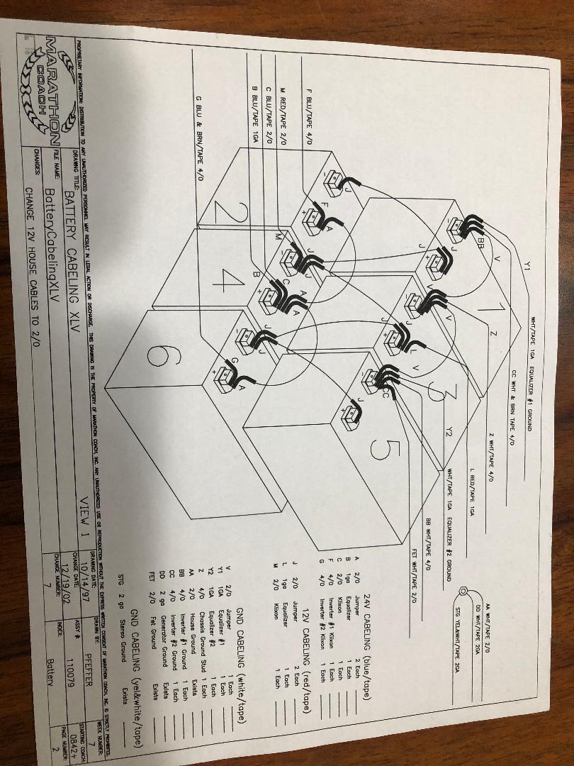
House Battery Cable Schematis Diagram XLV.jpgI own a 2000 Prevost Marathon Coach Motorhome. The system uses a proprietary communication system for batteries and cabin management. However, this communication system does not monitor anything but voltage and AMP's through 4 each FEM Current Transducers. . I would like to add a Victron battery monitor to system. There are 6 each 4D Lifeline batteries at 210 AMP's each for house. The existing house batteries are wired in 3 each Series producing 24VDC and 3 each parallel producing 12VDC. Attached is schematic of batteries. I just had to replace under warranty the three 12VDC batteries which Lifeline honored do to bad cell bringing all of them down over time. I need a more robust monitoring system to watch batteries . All I see on dash guage is voltages and amps being used. All I see at Inverter panels is Bulk and Float and charging voltages based on battery temperatures and inverter setup parameters. How do I wire in Victron. The Bus also has a 20K generator onboard.
asked
Need advice how to install a BMV Battery Monitor in my system
Hi @Travelingman. A BMV monitor needs it's shunt wired into a common earth to all the loads/charge you want it to measure. You have multiple earths all over the place, so it's not possible set up like that.
I guess that's what they did ~20 years ago. So pardon me for suggesting a 'redesign' of your system. The main reason is to avoid the 12V teeoff from one side of the 24V system, which is asking for batt imbalance issues. Those can kill batts.
I don't know what your 12V loads are, but these could be serviced by an Orion 24/12 dc>dc converter. Then have all your wiring heading off to relevant +ve and -ve buses. From a simple 24V dedicated 2S3P bank.
Your BMV could work with that, and you could even add a Victron batt balancer to optimize your mid-string V. (or use your BMV to at least monitor that).
I won't go on just yet, as you may reject this out of hand, or see other issues. Please come back..
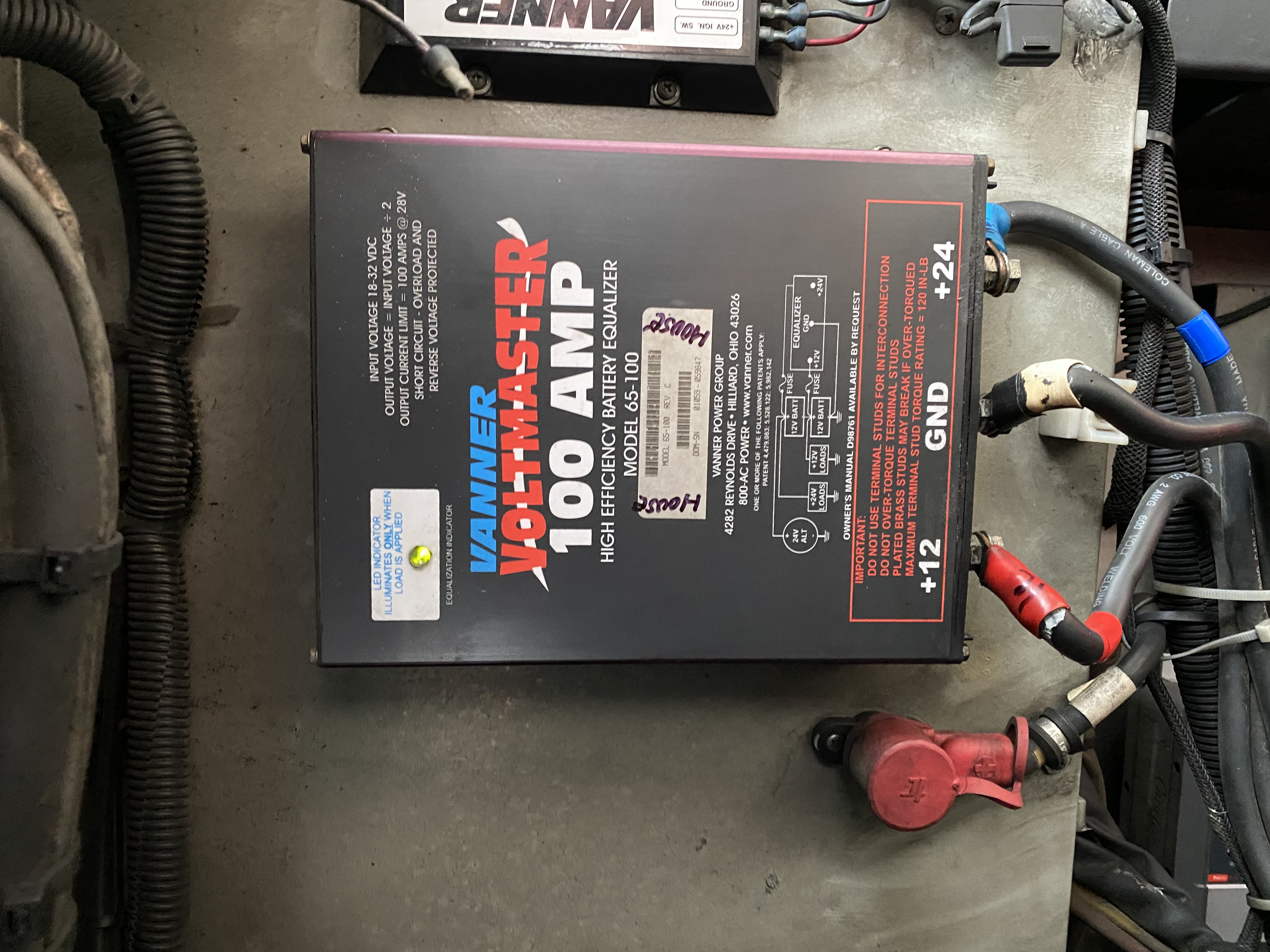
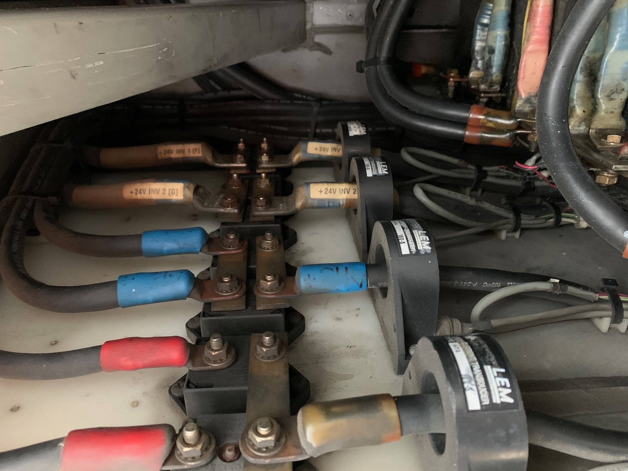
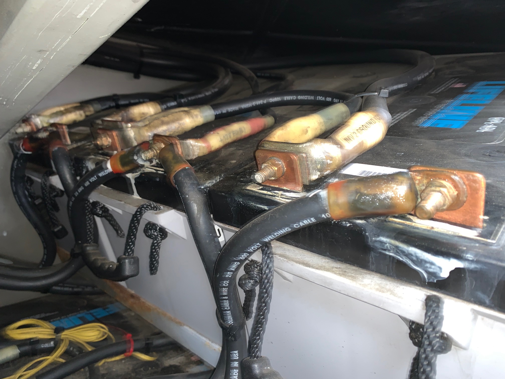
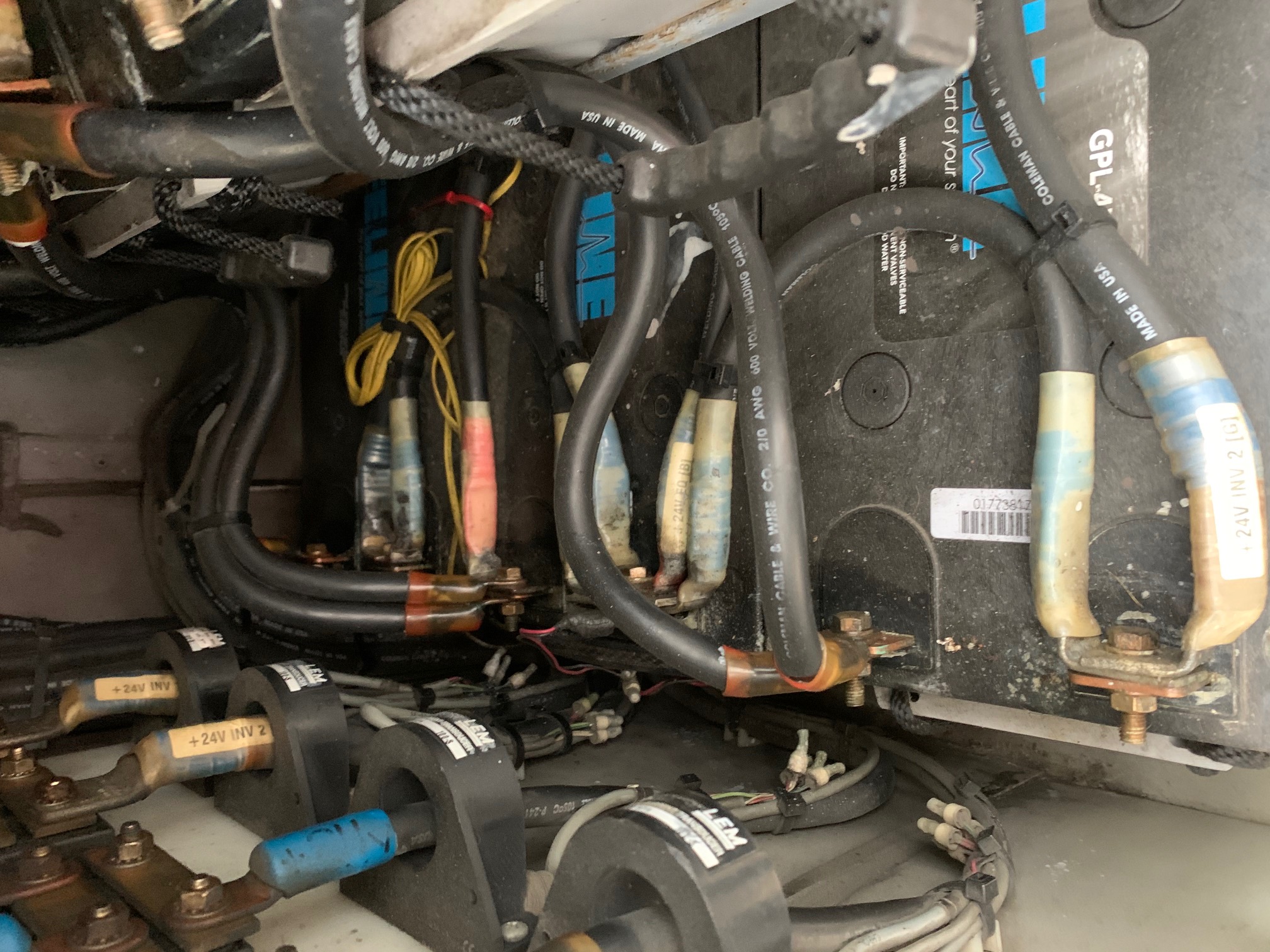
Thanks JohnC, Yes the twenty year old battery bay and wiring is a mess. Was probably state of the art in year 2000. The bay is located on passenger side bus just forward of engine bay. The inverters are located on driver side of bus and forward one bay. And forward of inverters same side is the 20 K generator Here are some pictures of what is happening in bay. There are multiple earth grounds the largest is the chassis ground just aft of battery bay in engine compartment. It comes of middle top battery. Here are some pictures. This is a electrical challenge for a basic DYI learn as you go person like my self. But a can read basic wiring diagrams. See my pictures to my answer. The labeled wiring on vertical wall going through transducers is for the positive 24VDC coming from inverters 1 and 2. The negatives for 1 and 2 are on batteries in top row. One going to farthest battery on top row and one to the nearest. The blue and red labeled cables going through current transducers are the outputs for 24vdc (blue) and 12vdc (red). The batteries are also being monitored by a Vanner 12-24 volt 100 AMP equalizer.Vanner Equalizer IMG_3645 (002).jpgChassis Ground IMG_3646 (002).jpg
Yeh, I looked up that Vanner device, and it explains a lot. Rather than an equalizer, I'd call it more a 'balancer', enabling that 12V teeoff. If it works, then should be fine. So I'll take back my 'redesign' suggestion.
The trouble is that the top row of batts has become the ground bus, and a BMV shunt only has one BATT terminal, so all grounds would have to be routed through it.
I count 11x ground wires, including 3x to a stud somewhere, and 1x heading off to a 'Klixon' (whatever that is).
A challenge it will be to sort them. I wouldn't call it a 'mess', just complexity.
Fun DIY project, and I wish you well with it. :)
Thanks JohnC, Yes the twenty year old battery bay and wiring is a mess. Was probably state of the art in year 2000. The bay is located on passenger side bus just forward of engine bay. The inverters are located on driver side of bus and forward one bay. And forward of inverters same side is the 20 K generator Here are some pictures of what is happening in bay. There are multiple earth grounds the largest is the chassis ground just aft of battery bay in engine compartment. It comes of middle top battery. Here are some pictures. This is a electrical challenge for a basic DYI learn as you go person like my self. But a can read basic wiring diagrams.
IMG_2144 Current transducers.jpg
IMG_2152 Top Row.jpg