question

doran avatar image
doran asked

Hoping for opinions on full Victron RV system plan

Dear all,


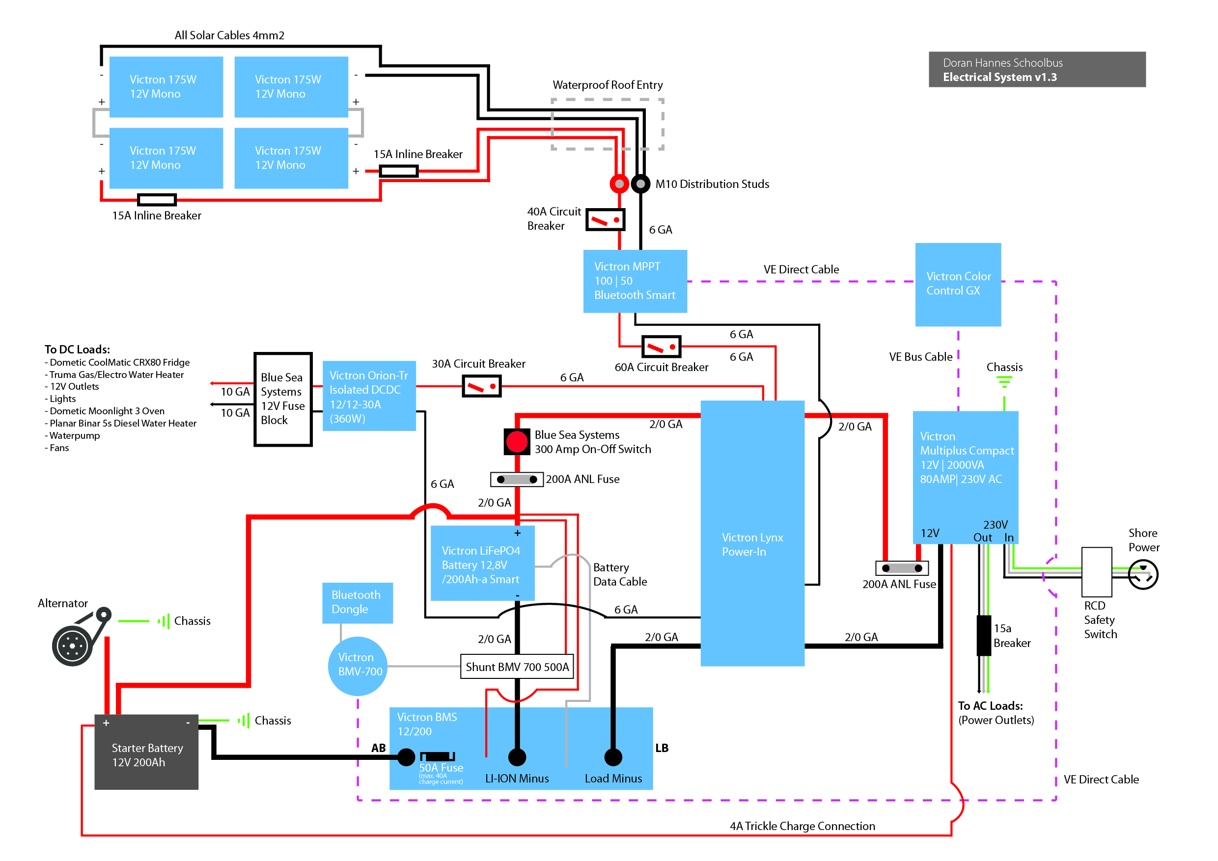
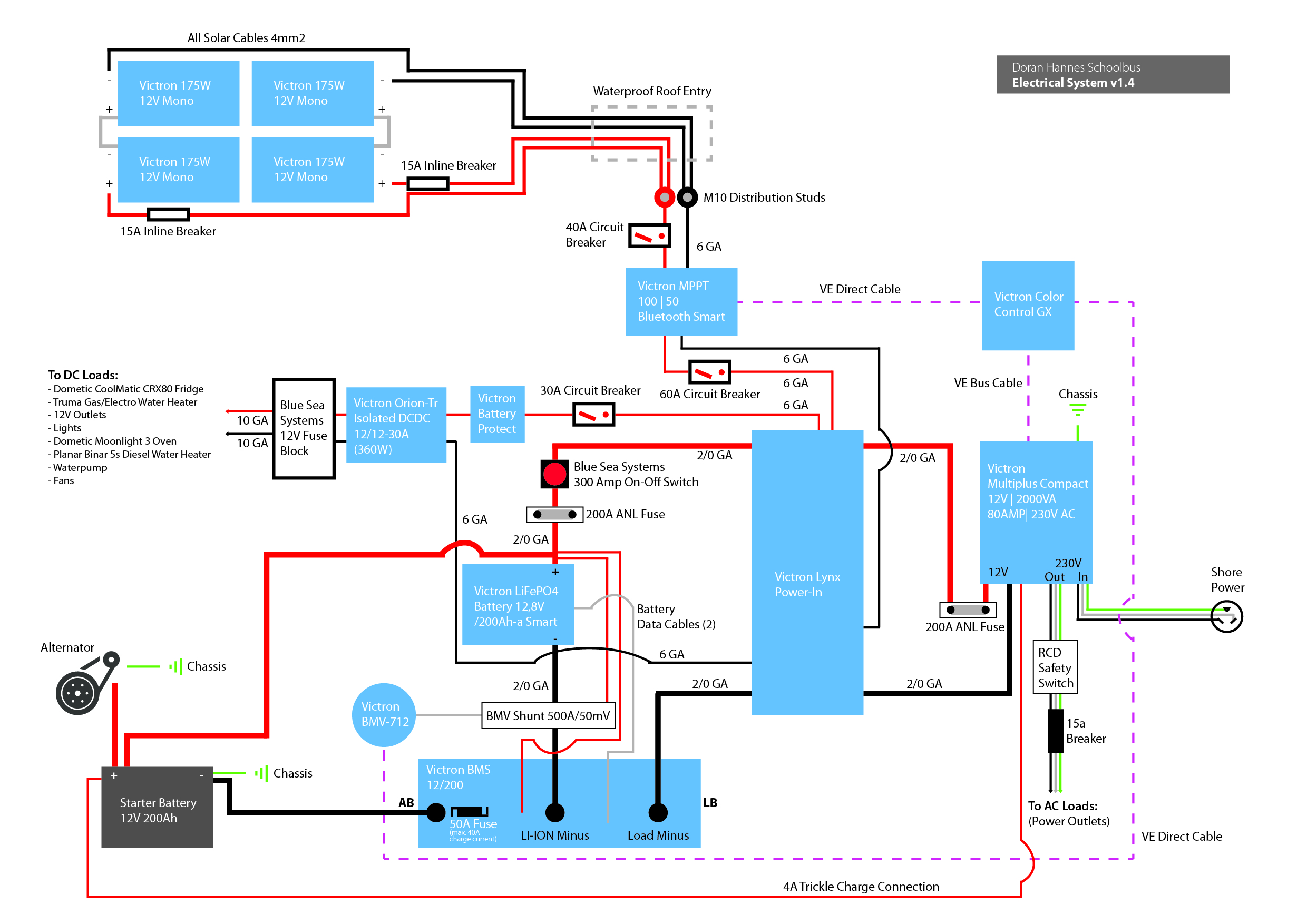
as I am new with all Victron components and quite francly electrics in general, I would really appreciate some opinions on my system plan. I have already put a lot of effort into this and read lots of articles and info but in the end every system is individual in itself and I am by far no expert yet.

I am planning to install all this into a bus that I am currently converting into an RV in Germany. I'm saying that to make clear that there is no current "house electricity" in the bus except cables throughout the walls to all appliances and outputs. For all 12V wiring I ran positive AND negative wires, so I guess the Orion DCDC converter might be an unneeded add-on in my case.

I don't really have many specific questions anymore. I was more hoping for someone with experience in Victron equipment to approve/or help improve my plan.


The only specific questions I am left with concerns the 4A trickle charge output of the Multiplus. Is it okay to just hook this up to my start battery positiv or do I need to be concerned about overcharging this battery once full?


I thank everyone who might get involved and look forward to any input you all might have.


Cheers,

Doran

victron productssystem design
2 |3000

Up to 8 attachments (including images) can be used with a maximum of 190.8 MiB each and 286.6 MiB total.

4 Answers
Elimac avatar image
Elimac answered ยท

Nice project!

At first glance, I just add one comment: I also like to add an RCD on the Multiplus 230V output. When in inverter mode, the one in the input will not protect against current leakage. I use 30mA sensitivity in both sides of the Multi.

5 comments
2 |3000

Up to 8 attachments (including images) can be used with a maximum of 190.8 MiB each and 286.6 MiB total.

Elimac avatar image Elimac commented ยท

I would like to hear about the issue of ground. Is is best to let the DC side floating or should one tie the negative to chassis/ ground?

0 Likes 0 ยท
Matthias Lange - DE avatar image Matthias Lange - DE โ™ฆ Elimac commented ยท

We always connect the battery negative and the PE to the chassis.

0 Likes 0 ยท
doran avatar image doran commented ยท

Hey Elimac. Cheers for your comment also. That seems pretty logical. I had not thought about that. I could just add a second RCD with the other breakers on the converter output side. Thanks!

I was also wondering if I should ground all my negatives to the chassis. But if I'm not wrong that seems to circumvent the connection that my starter battery has with the house battery through the BMS and would therefore disable the needed safety function that the BMS provides to not pull too much charge from the alternator/start battery. Maybe someone else can comment on that one.

0 Likes 0 ยท
Elimac avatar image Elimac commented ยท

Just to clarify one detail: the RCD I have on my Multiplus input is not exclusive for it. It is on the AC distribution board I have nearby, and the Multiplus is just another load, when in charge mode. I would still recomend to have RCD on input (either dedicated or not) to be on safe side in case something goes wrong. I do have an electrode for Multi Earth connection (mine is a fixed installation).

0 Likes 0 ยท
doran avatar image doran Elimac commented ยท

In my case the AC input goes directly into the Multiplus. I guess in that case it makes sense to just put the RCD on the output of the Multiplus instead of the input like M.Lange was saying.

0 Likes 0 ยท
spirou avatar image
spirou answered ยท

I will add that using a BMV700 + dongle doesn't make much sense compared to 712. The combo is only slightly cheaper but 712 uses less to power itself and leaves you with ve.direct port free should you wish to extend the system later. Also slightly easier to set up BT and there is no extra cable for no reason.

3 comments
2 |3000

Up to 8 attachments (including images) can be used with a maximum of 190.8 MiB each and 286.6 MiB total.

doran avatar image doran commented ยท

Hey Spirou. Thanks for your thoughts. I am totally with you on that one. Unfortunately I had already bought the BMV700 a while back without realizing the difference. I wasn't sure if it was worth swapping to the 712 instead of adding the dongle.

0 Likes 0 ยท
Matthias Lange - DE avatar image Matthias Lange - DE โ™ฆ doran commented ยท

You can't use the BT-dongle and the the VE.direct connection to the CCGX at the same time because the BMV only has one VE.direct port.

0 Likes 0 ยท
doran avatar image doran Matthias Lange - DE โ™ฆ commented ยท

Good point! Thank you!

0 Likes 0 ยท
Matthias Lange - DE avatar image
Matthias Lange - DE answered ยท

Mit einem 2000VA Multi sollten sie nicht das BMS 12/200 nutzen, das werden sie beim anschlieรŸen des Multis durch den groรŸen Strom zum aufladen der Kondensatoren zerschieรŸen.
Das hatten wir leider auch schon ein paar mal. Ein VE.Bus BMS wรคre da die bessere Wahl.

Sie schreiben etwas von einem Bus, sicher das dieser nicht auf 24V lรคuft?

Ein RCD am Eingang des Multis macht nicht viel Sinn, der gehรถrt an den Ausgang.

Wozu der DCDC-Wandler? Bis auf evtl. das Licht sollten alle Komponenten fรผr den Spannungsbereich von etwa 10-15V ausgelegt sein, sind ja alles Gerรคte fรผr den Camping-/Caravanbereich.

Ein Batteriewรคchter fรผr die 12V Verbraucher zum Unterspannungsschutz sollte noch eingeplant werden. Ja, das BMS schaltet bei Unterspannung auch ab, aber erst wenn wirklich kritische Werte erreicht werden, soweit sollte man es aber im normalen Gebrauch nicht immer kommen lassen.


With a 2000VA Multi you shouldn't use the BMS 12/200, if you connect the Multi you will probably destroy the BMS because of the high inrush current to charge the capacitor within the Multi.
We already had this a few time. It's better to use a VE.Bus BMS.

You wrote it is a bus, sure the bus isn't 24V?

A RCD at the input of the Multi don't makes sense, the RCD belongs to the output.

Why the DCDC converter? Except eventually the light all components should work with a voltage range of 10-15V due this all are devices for camping/caravan.

You also should use plan with a low battery protect for the 12V loads. Yes, the BMS also cuts off at low battery voltage but only at critical values, for normal usage you shouldn't go to this SCO every time.

4 comments
2 |3000

Up to 8 attachments (including images) can be used with a maximum of 190.8 MiB each and 286.6 MiB total.

doran avatar image doran commented ยท

Thanks for your input.

Could you explain the problem with the Multiplus 2000 and the 12/200 BMS a little more? If that was not possible I would have to add the VE.Bus BMS and use the 12/200 for charging through my alternator only? Another expense and addition in the system...

The bus (old American schoolbus) runs on 12V, not 24V.

Someone else commented to add an additional RCD to the output. Does it make sense to put one on the input and output to be safe on all sides?


If I connect my negativ busbar within the Lynx Power-In with the chassis, the connection of the starter battery through the BMS would be compromised right? Also in that case the DCDC converter would become a requirement to not drain my starter battery with my 12V loads as far as I understand. Why shouldn't I leave the system floating? I did run positive and negative cables everywhere already.


Is it really necessary to add another battery protect between the 12V loads and the lithium battery?


Thank you so much for your help!

0 Likes 0 ยท
richard-owens avatar image richard-owens doran commented ยท

You should definitely have isolation between your lead acid starting battery and any lithium batteries in your system. Even LiFePO4 batteries, which represent a good drop in replacement for lead acid batteries do not have the exact same voltage profile, so are not compatible with each other directly.

Although, while the bus is operating, the alternator's 13.8 volt output is compatible for charging your LiFePO4 batteries, with one major caveat - LiFePO4 batteries can accept as much current as your alternator can provide, so extended charging from your alternator could present a danger to your alternator, causing it to overheat and possibly fail. For this reason, if it is your intention to use your alternator to charge LiFePO4 batteries, your alternator should be oversized and you should monitor its temperature while charging, so that the isolator can disengage charging should the alternator become overheated. The larger your battery bank, the greater the danger to your alternator, as well as the wires you're using to charge the batteries.

I would recommend some method of limiting the charging current required from the alternator. One potential method of accomplishing this - that does cost some money - is the use of a pure sine wave inverter to convert the DC from your bus's alternator to AC and then use that AC to power a proper LiFePO4 battery charger with a specific charge current rating. This puts you in control over the amount of demand being placed on your alternator and is likely less expensive than replacing your alternator for your bus or melting the insulation on the wires you're using. Just make sure that the battery charger will draw no more than 50%-75% of the capacity of the inverter, so it isn't being pushed too hard. Remember, just because an inverter might be rated at 1000 watts does not mean it can deliver 1000 watts indefinitely. The more conservative you are in this regard, the more reliable your solution will be. I hope this helps.

0 Likes 0 ยท
doran avatar image doran richard-owens commented ยท

Thanks Richard. The BMS serves this function in my system as the possible charge current is regulated by the size of fuse you put into the AB side of the BMS.

0 Likes 0 ยท
Matthias Lange - DE avatar image Matthias Lange - DE โ™ฆ doran commented ยท

Ok, english only. I thought because you wrote you will build it in Germany it is easier for you and me to write in german. :)

In the moment you connect the Multi to the battery the capacitors within the Multi charging up and that cause a very high current flow for a few ms and this current can damage or destroy the BMS.
You can give it a try but I would not recommend it. As I wrote above, we had this problem a few times.
You can only connect one BMS to the battery.(In the schematic in the BSM 12/200 manual is a Multi 12/2000 connected to the BMS ... maybe Victron has changed something in the past, I don't know)
Maybe @Daniรซl Boekel (Victron Energy Staff) can write something to this topic.

A RCD on the input is not necessary if you go from the shore power socket directly into the Multi.

Yes, if you use the BMS 12/200 you shouldn't have a connection to the csasssis on the LB side.

It is not really necessary to add a battery protect but I would recommend it.
The BMS only cuts off the loads at critical states and I recommend to not go so low every time.
With the BP you can cut off the load before the BMS has to do it.

0 Likes 0 ยท
doran avatar image
doran answered ยท

Here is an updated plan. I have swapped the BMV-700 to a BMV-712 and removed the Bluetooth Dongle, added a Battery Protect to the 12V load side and moved the RCD to the output of the Multiplus.


Open questions atm:

1) Do I need to be worried about overcharging my starter battery with the 4A trickle charge output of the Multiplus?

2) Does anyone know more about possible damage to the BMS 12/200 through high current flows from the Multiplus as M.Lange mentioned in his comments?


8 comments
2 |3000

Up to 8 attachments (including images) can be used with a maximum of 190.8 MiB each and 286.6 MiB total.

Sten avatar image Sten commented ยท

As M.Lange wrote, it's not a god idea to connect the multiplus through the BMS.

It would be a mutch better solution to connect the minus of the multiplus directly on the load side of he BMV 712 shunt.

The Orion tr is not required, unless you need a stabilized suply.

0 Likes 0 ยท
Matthias Lange - DE avatar image Matthias Lange - DE โ™ฆ Sten commented ยท

No, if he do so, the battery isn't protected against overcharging/discharging by the BMS anymore!

0 Likes 0 ยท
Sten avatar image Sten Matthias Lange - DE โ™ฆ commented ยท

should the multiplus not take care of this itself?

0 Likes 0 ยท
Matthias Lange - DE avatar image Matthias Lange - DE โ™ฆ Sten commented ยท

It should, yes. But what if the Multi is faulty?
The BMS also monitors the voltage/temperature of the individual cells.
If the cells get out of balance an during charging one cell gets to high the BMS will stop the charging to let the cells balance.
The BMS also will cut off charging/discharging if the temperature gets to low/high.
All this the Multi can't do on its own, that's the reason you need a BMS.

0 Likes 0 ยท
Sten avatar image Sten Matthias Lange - DE โ™ฆ commented ยท

you are right, I take back my answer to that. :-)

0 Likes 0 ยท
Sten avatar image Sten commented ยท

Another thing I just saw, is your fuse at the multiplus. If you se in the manual for the 12/2000 the recomented fuse is 300A. Section 4.2 in the manual. And last you have a redundand fuse. You only need the ANL fuse at the battery, the one at the multiplus is not needed..

https://www.victronenergy.com/upload/documents/Manual-MultiPlus-Compact-2000-230V-EN-NL-FR-DE-ES.pdf

0 Likes 0 ยท
tromblrl avatar image tromblrl commented ยท

Did you install this electrical system? How did it go? Would you make any changes? I am planning the same system for my van.

0 Likes 0 ยท
doran avatar image doran tromblrl commented ยท

Hey there. I did! All in all everything seems to work just fine. I have been using the system daily for the last 7 month (full time living in my bus through the winter). The solar panels are not yet installed though, so it has been feeding from the grid most of the time.

I suppose as other already commented here, the Orion DCDC converter wasn't necessary! Otherwise I have been running two electrical heaters for quite a while as I had trouble with my diesel heater. That was never planned in the design of the system and a few times the converter was maxed out. Depending on what you are planning to use you might want to consider a bigger size, but for most things in a camper it should be fine.

Also I think the configuration with the BMS 12-200, even though it seems to work fine for me might be a bit outdated. I'm looking forward to getting the solar panels hooked up soon and to disconnect from the grid whatsoever.

All the best,

Doran

0 Likes 0 ยท

Related Resources

Additional resources still need to be added for this topic