question

metal-snapper avatar image
metal-snapper asked

Isolation transformer earth connection

Hi all,

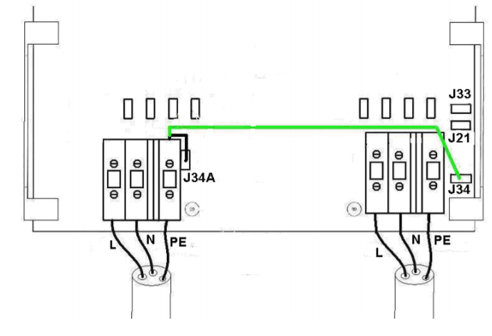
Just confirming here that when my boat is floating on the water there should be a link from the input PE terminal to J34a.

So, the earth wire from the shore power supply flex is connected to the input PE terminal and I make a small wire up with a female spade connector from this input PE terminal and connect it to J34a?

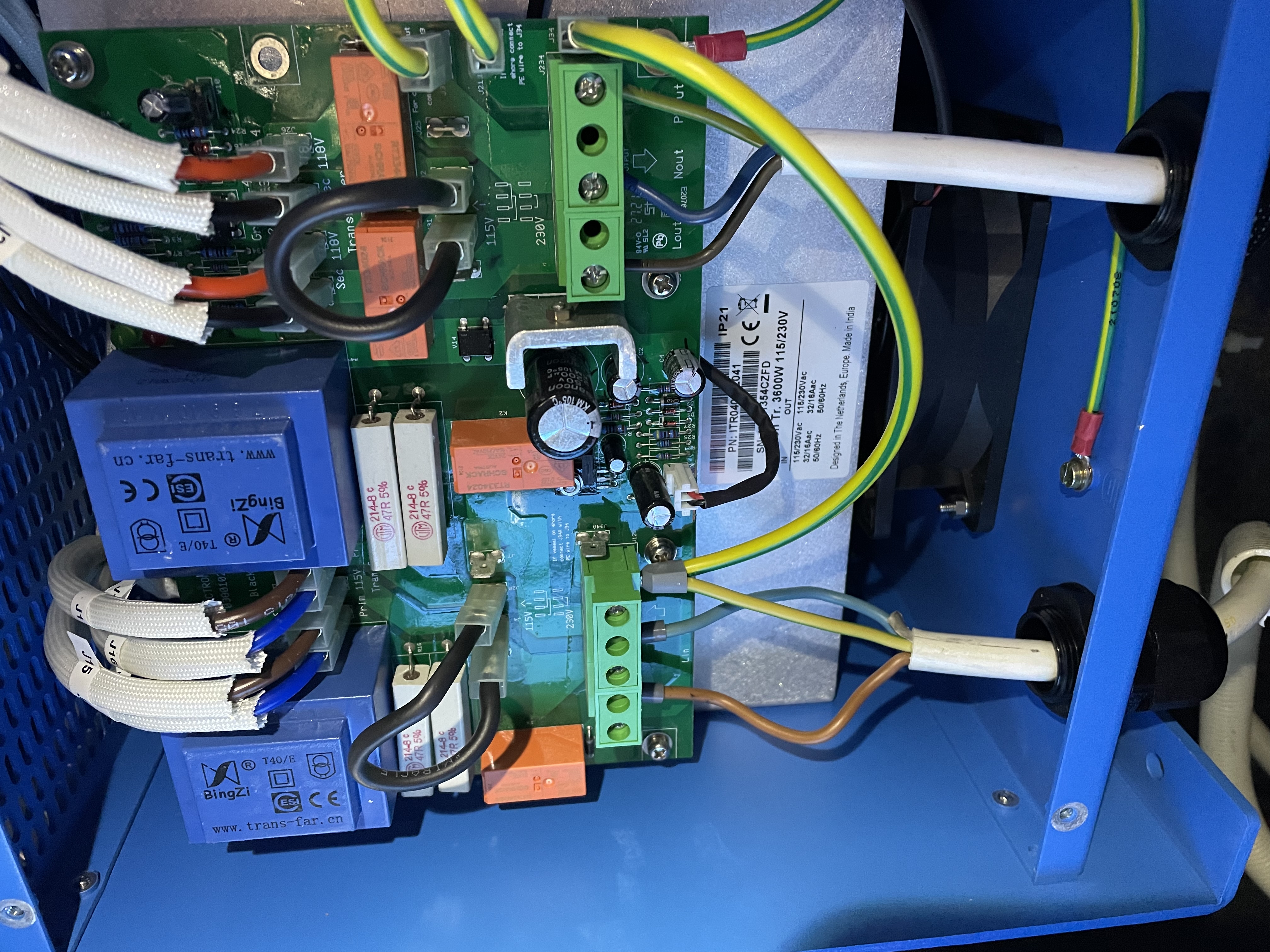
This transformer is not the auto 115v - 230v switching model

Many thanks

installationIsolation Tranformer
2 |3000

Up to 8 attachments (including images) can be used with a maximum of 190.8 MiB each and 286.6 MiB total.

8 Answers
jwfrary avatar image
jwfrary answered ·

Hi


Manual shows a green and a black wire.


Black wire installed all the time


Green wire installed when your ashore as otherwise there is no route to earth and your rcd or rcbo wont trip

2 |3000

Up to 8 attachments (including images) can be used with a maximum of 190.8 MiB each and 286.6 MiB total.

Johannes Boonstra (Victron Energy Staff) avatar image
Johannes Boonstra (Victron Energy Staff) answered ·

Hello, under the normal usage of the transformer there is NO wire from PE input J34A to PE output J34! as this will un-isolate the system, while the reason for the transformer is to isolate.


ONLY when the boat is NOT in the water and a shore connection is used, it can theoretically happen that you work with tools or something directly plugged in the shore power (and not current doesn't flow through the transformer) .

At an electrical fault the RCD on shore would not trip as the hull isn't grounded to the same potential, so the whole hull becomes "live".

Then (and only then) the J34a must be connected to J34 to bridge the transformer. (see picture)

There is no need for us to supply this lead as it might work confusing and the jumper remains "IN".


ground.png (91.5 KiB)
4 comments
2 |3000

Up to 8 attachments (including images) can be used with a maximum of 190.8 MiB each and 286.6 MiB total.

cardy01 avatar image cardy01 commented ·

To confirm:

The black "wire" from PE in to J34A shown above is in fact hard-wired in the transformer pcb? In normal use afloat nothing should be connected here?

The green/yellow jumper (supplied with my 2000VA transformer) is only needed from J34a to J34 when the boat is ashore?

0 Likes 0 ·
h2operator avatar image h2operator commented ·
Johannesburg, My application is non marine, I am using the transformer ITR2000 for a pond pump to prevent Neutral to Earth Voltage, I had a problem where my fish were being shocked. My question is with ground option should I use to still isolate the neutral and not have a problem with a difference in ground potential at the submersible pump? I am thinking that having the transformer in “ in water” mode would cause a difference in ground potential at the pump and present a shocking hazard in the event of a ground fault. The pump is 115 vac plugged into a GFCI receptacle. This is an application in the US.

Thanks for any advice, Lance

0 Likes 0 ·
h2operator avatar image h2operator h2operator commented ·

Johannes, sorry for the spellcheck issues. My question is “which” ground configuration should I use in this application.

Thanks, Lance

0 Likes 0 ·
h2operator avatar image h2operator commented ·

New question, my original intent was to remove neutral to earth voltage but regardless of the ground configuration I’m still seeing voltage on the output neutral and ground.

My technician in the US thought this would not happen, any ideas?


0 Likes 0 ·
andrewp avatar image
andrewp answered ·

I have the same issue - the manual is not clear on this. It describes ‘the PE wire coming from the input PE terminal’ but this doesn’t exist. Why would victron expect the user to make up this cable when all the rest are supplied?

1 comment
2 |3000

Up to 8 attachments (including images) can be used with a maximum of 190.8 MiB each and 286.6 MiB total.

jwfrary avatar image jwfrary commented ·

Came with the last 7000watt one I installed.

However.

I normally wire up to a switch so when you come out of the water you just turn the big red switch, no messing with the front panel.

0 Likes 0 ·
socalsker avatar image
socalsker answered ·

Andrew, did you ever find an answer to this? I have been looking everywhere for information on whether or not we are supposed to direct connect this PE to jumper J34A??? Seems odd that Victron doesn't include this wire, and I agree that the manual is not clear on this. Thanks.

2 |3000

Up to 8 attachments (including images) can be used with a maximum of 190.8 MiB each and 286.6 MiB total.

Pierre Cervenka avatar image
Pierre Cervenka answered ·

Hi!

I went in the same issue with my Isolation Tr. 3600W Auto 115/230V (SKU: ITR050362041 ).

With this particular model, the instructions are engraved on the board, which is pretty clear, but I agree the manual does not describe the actual setup:

On the right side of the input terminal block, there are two prongs labelled J34A and J34A1. I checked that the former, J34A, is internally wired with the PE Input (no resistance)

On the right side of the output terminal block, there is one prong labelled J34. I checked also that J34 is internally wired with the PE output (no resistance)

In the water, connect J34A with J34A1 with the short supplied yellow-green wire.

On dry shipyard, connect J34A with J34 with the long supplied yellow-green wire.

The two solutions are mutually exclusive, because only one wire can be plugged into J34A: on the dry, J34A cannot be connected to J34A1; conversely, in the water, J34A cannot be connected to J34.

That's what I understand how it works.

**** Please tell me if I am wrong! **********

If this is ok, it would be less confusing if the manual was clearer on that point

(by the way, I have another issue with my transformer, see my post "Isolation Transformer help")

2 |3000

Up to 8 attachments (including images) can be used with a maximum of 190.8 MiB each and 286.6 MiB total.

Pierre Cervenka avatar image
Pierre Cervenka answered ·

My comment was (partly) irrelevant with respect to the manual.

My brand new Isolation Transformer (Auto) bought in October 2019 was delivered with the 2012 version of the manual, whose lack of precision triggered my comment.

Because of Covid related delays, I just installed in September my transfo, which is not working (see my "Isolation Transformer Help" post). Up to now, the only response of Victron (as reported by the distributor) has been:

1) to claim that the problem is caused by an improper input connection (!!!)

2) to send the manual, which is supposed to solve my problem if properly followed

It gave me the opportunity to check that the up-to-date manual describes now properly the grounding settings of the auto version (which was anyhow not much difficult to decipher previously), at least in English an Dutch, but the French part provides always the same loosy description as in the old release.

It "seems" now Victron is studying hard my case, to check that the guarantee procedure could be started... (problem raised at the distributor Friday 09/18 early in the morning, still in the blue this Wednesday 09/30 at night...

2 |3000

Up to 8 attachments (including images) can be used with a maximum of 190.8 MiB each and 286.6 MiB total.

hakanlarsson65 avatar image
hakanlarsson65 answered ·

Hi

I can still not figure out if the black AND green wire should be connected when on shore. There is no connection between PE in and J34A ( I have measured) so I need to make one wire from PE in To connector. If both black and green should be connected it will be narrow in the jumper. Attached a picture how I think right know. When go in to water I move the cable from J34 to J34A. Right?8a77b2e7-0260-4382-bd8c-4e4dafc9e6ff.jpeg


2 |3000

Up to 8 attachments (including images) can be used with a maximum of 190.8 MiB each and 286.6 MiB total.

christern avatar image
christern answered ·

Please forgive me if this is wrong but as I see it you have connected the yellow/green cable from the AC incoming ground wire to the AC outgoing ground wire. This is not correct and will, I believe, not make the isolation transformer separate from the shore power in relation to grounding.

There are “male push-on jumpers” next to both the incoming and outgoing AC cables labelled J34 and J34A. When on shore these should be connected using the yellow/green cable that came with the transformer (in most cases I believe).

When in water you should remove this cable and add the black one between the PE output and J34A.

2 |3000

Up to 8 attachments (including images) can be used with a maximum of 190.8 MiB each and 286.6 MiB total.

Related Resources

Additional resources still need to be added for this topic