question

michaelsamer avatar image
michaelsamer asked

VE.Bus termination

Hi at Victron

I'm wondering why the VE.Bus (e.g. CCGX to Mulit-II) is not terminated any longer (while it was in the earlier implentations. While using EIA-485 it should be terminated (e.g. ISBN 978-3-8348-0425-9 or https://en.wikibooks.org/wiki/Serial_Programming/RS-485#Termination) on both ends of the chain preferable active (on longer connections) or passive (very similar to CAN). As most specs it will work even when it is not connected as long as the load is low and the cables short so reflections on the two ends are not excessive.

But why did you stop using (passive I guess) Terminators?

Cheers

Michael

VE.Bus
2 |3000

Up to 8 attachments (including images) can be used with a maximum of 190.8 MiB each and 286.6 MiB total.

6 Answers
Matthias Lange - DE avatar image
Matthias Lange - DE answered ·

As long as I use Victron (more than 10 years) there was never a termination required for VE.Bus.

2 |3000

Up to 8 attachments (including images) can be used with a maximum of 190.8 MiB each and 286.6 MiB total.

mvader (Victron Energy) avatar image
mvader (Victron Energy) answered ·

Hi, I can’t remember ever using external terminators on VE.Bus. And I’m sorry but I dont know why we don’t. Perhaps we have a terminator on each board.

We do for VE.Can, perhaps that is where you’ve seen external ones.

Best regards, Matthijs

2 |3000

Up to 8 attachments (including images) can be used with a maximum of 190.8 MiB each and 286.6 MiB total.

michaelsamer avatar image
michaelsamer answered ·

Hi mvader,

I'm more in a reason question than a technical one. I'm using the ProfiBus on a professional basis and as it's using EIA-485 as well I wondered. No termination even on short bus lenght (10m) would be treated as bad design in my (automotive) branch. Maybe you are not using the VE.Bus in such long distances so data corruption (reflection & load) is not imanent to cause a problem. Max. 9 Multis and one CCGX doesn't sound like 20m over all. Terminating all devices would cause unreasonable dampening of the signal which causes more problems than it would solve.

CAN (as well intensly used by me) explicitly calls for termination. Btw. CAN possibility was one of the reasons for me to go for Victron (even when I don't use any in my CCGX).

Cheers

Michael

1 comment
2 |3000

Up to 8 attachments (including images) can be used with a maximum of 190.8 MiB each and 286.6 MiB total.

mvader (Victron Energy) avatar image mvader (Victron Energy) ♦♦ commented ·

Hi Michael, thank you for the input. Although I dont know the details, I do know that considerable effort went into that, and I have full confidence in the developer that is responsible for this.

Sorry that I can’t give you the details but I don’t want to bother R&D for it.

You’ll have to trust us on it too. ;o)

Best regards,

Matthijs

0 Likes 0 ·
michaelsamer avatar image
michaelsamer answered ·

Hi M.Lange
I was informed by my VE Partner that it was once terminated. As mentioned the EIA calls for it, so I wondered why it was not planned in the design phase. As mentioned before maybe the VE.Bus will not reach lenght/load or Speed which causes data corruption without termination
Cheers
Michael

2 |3000

Up to 8 attachments (including images) can be used with a maximum of 190.8 MiB each and 286.6 MiB total.

udo229 avatar image
udo229 answered ·

I have now a problem on my installation which could have to do with termination problems.

i have an octo gx and three multiplus II. On installation two years ago the ve.bus interfaces of the first two Multis was blown, maybe due to an interrupted minus—cable. The interface was repaired by victRon, so my dealer told me. Now I have more and more troubles , after few minutes an ve.bus—error occurs ( in the range #1 to #25) resetting, new cabling, tightening of all powercablescrews, nothing helps. Reconfiguring to an one—phase—system with only one multi works without errors. I tried every of the three for several hours.

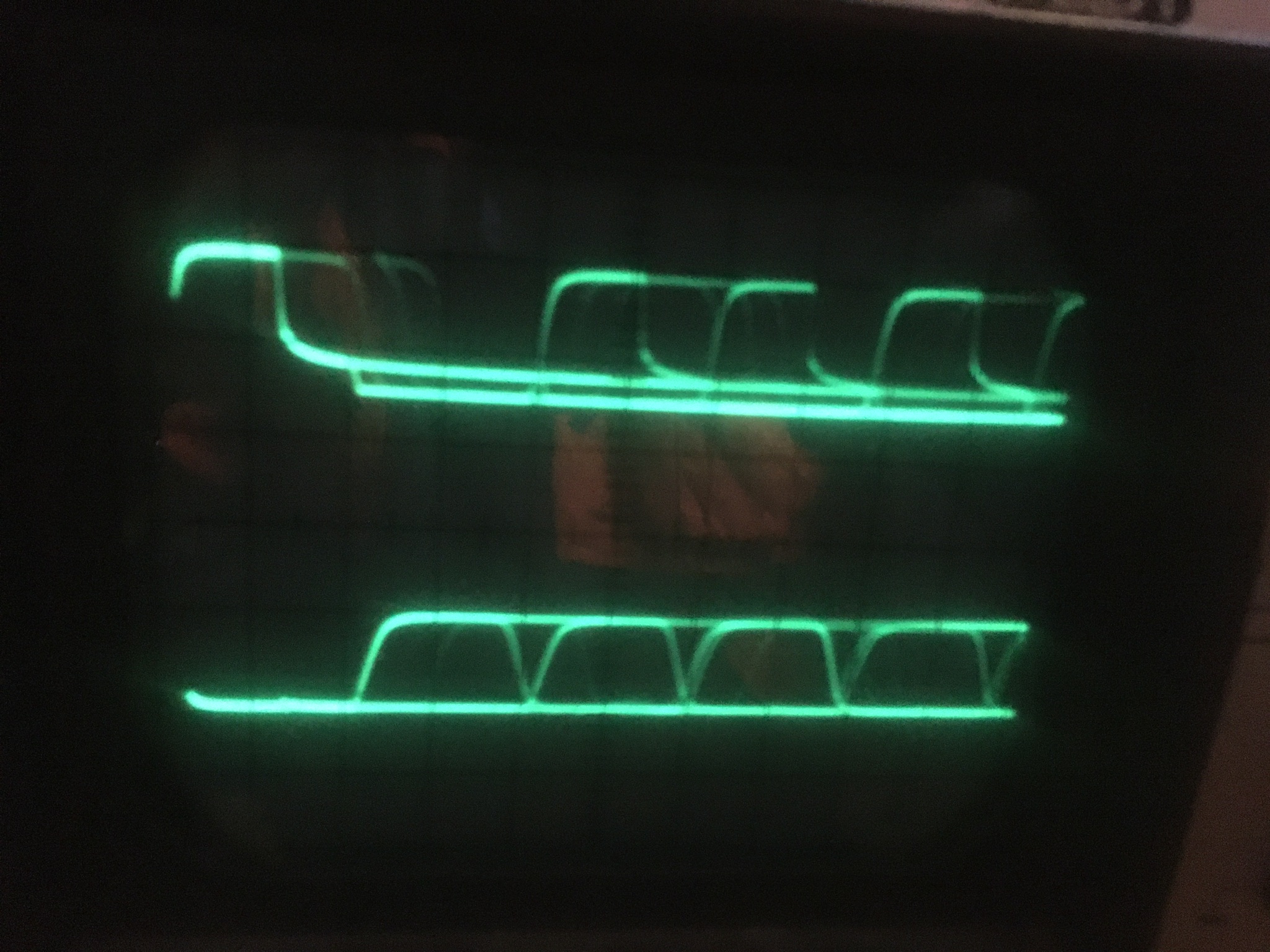
tested the ve.bus/ rs485 signals with an oscilloscope . The signals on pin 5 had a very slow falling flank on the repaired two Multis, the signal on number three looked much more rectangular.
after switching off the Multis and disconnecting of all ac/dc power I measured the resistance of Pin 4 and 5 to ground. On the repaired two Multis it was more than 13 kiloohms pin4/pin3 and pin5/Pin3. On the third multi it was 240 ohms pin4/ pin three and 74 ohms pin5/ pin 3.

i think there is a fault somewhere in the interfaces.
can anybody help me?


Upper photo is pin 5 of the third multi,

photo below on the first and second, once repaired multi. Same timebase, trigger, amplification. Doesn‘t look too rectangular to me...

532a29d3-d913-41c4-93e9-80ee4e51b986.jpeg7b631d68-6839-42b8-b6c3-a4a3d3627b2d.jpeg


3 comments
2 |3000

Up to 8 attachments (including images) can be used with a maximum of 190.8 MiB each and 286.6 MiB total.

michaelsamer avatar image michaelsamer commented ·

Hi Udo229

rectangular is the wanted signal (everywhere in digital circuits), but rarely the usual [in GHz CPUs it looks awful..]. The slow flanks are normally caused by long/capacious cables (e.g. not drilled). I basically asked (as written above) as the EIA gremium demands it:

https://de.wikipedia.org/wiki/EIA-485#/media/Datei:Rs485-bias-termination.svg

As I build my own cable (because I missed screening of the cable, which I found very important on High Amperage switching circuits as the MultiPlus is), so I included the asked termination three R's just to honour the specs. As it worked instantly I never changed it since... I guess the termination is only needed on longer cable length and rarely somebody have problems. Victron did not respond to the question about EIA specs, so maybe it rarely surfaces....

While I own (as electronic engineer I have to have) a Oszi, I rarely use it nowadays and it's perfectly wrapped....

What I would see: the falling flank is very long trail. Afaik this is not critical as RS485 used level triggering and not edge trigger (where such a sleeve must have bad impact).

Did you measure Signal X to GND or between the X/Y as it should (as RS485 is a sym. signal). The simplest termination (have to be...) 120Ohm between X and Y; I crimped two RJ45 (=one on each end) with the three Resistors, but one would be OK as well. I never measured the internal of my Victron devices ( I guess they developed to Specs), but wanted to be true to my profession, so I stayed with the EIA Specs. As it worked I never doubt my good doing, even when Victron maybe used different RS485 driver. You could put two 120Ohm resistor in your network (RJ45 crimps are very easy to get; or use an old network cable) and repeat the test. I doubt the signal could get worse.

This is my 50ct.

Victron is the MFC and knows his stuff surely better than a "try to be electronic" with doubts.

Cheers

Michael


P.S.: Another doubt would be the CAN termination (in my CCGX): it's included, but if CAN is not used the manual doesn't tell you to terminate anyway (which is needed by the specs as well so the transceiver is not broadcasting errors).


0 Likes 0 ·
udo229 avatar image udo229 michaelsamer commented ·

Hello Michael!

Thank you for the elaborated answer.

The point is:

I measured the signal without any cabling.

I cut an Ethernet- cable and used the open ends to connect the oszilloscope. Yes, I measured the active pins to ground.

I plugged the cable into all the Multis one after the other without any other ve.bus- cabling. So the difference between the two photographed signals can‘t be explained by long cables. In my Setup, the three Multis and the octo were connected with three 1 meter network cables.....

And I wonder about the measured resistances too, 13 kiloohms to 240 ohms on the same pins on different Multis sounds suspicious. Can you measure those resistances on your Multis?

I hope someone from Victron could help absolut it. My dealer suggested to mail him all three Multis and the octo, which means i wI’ll have no power for my car and other appliances.

I think one or two of the Multis have a faulty ve.bus interface and wound like to identify it/them.
Regards

udo


0 Likes 0 ·
michaelsamer avatar image michaelsamer udo229 commented ·

Hi Udo

to see the true signal (a differential) you have to measure the two data pins.

With two different transceivers (e.g. low power circuits vs. standard) it could be normal to measure two different resistors. You have measured while powerless I hope to t have a real resistance measurement. With the same modell all resistors/circuits should be absolutely the same; different models/types may differ.

While I'd test it, mine are essential for my housepower here as I'm using my three multiplus as only source of current in my house. So it's always powered and no downtime planed.

Cheers

Michael

0 Likes 0 ·
udo229 avatar image
udo229 answered ·

Hello!

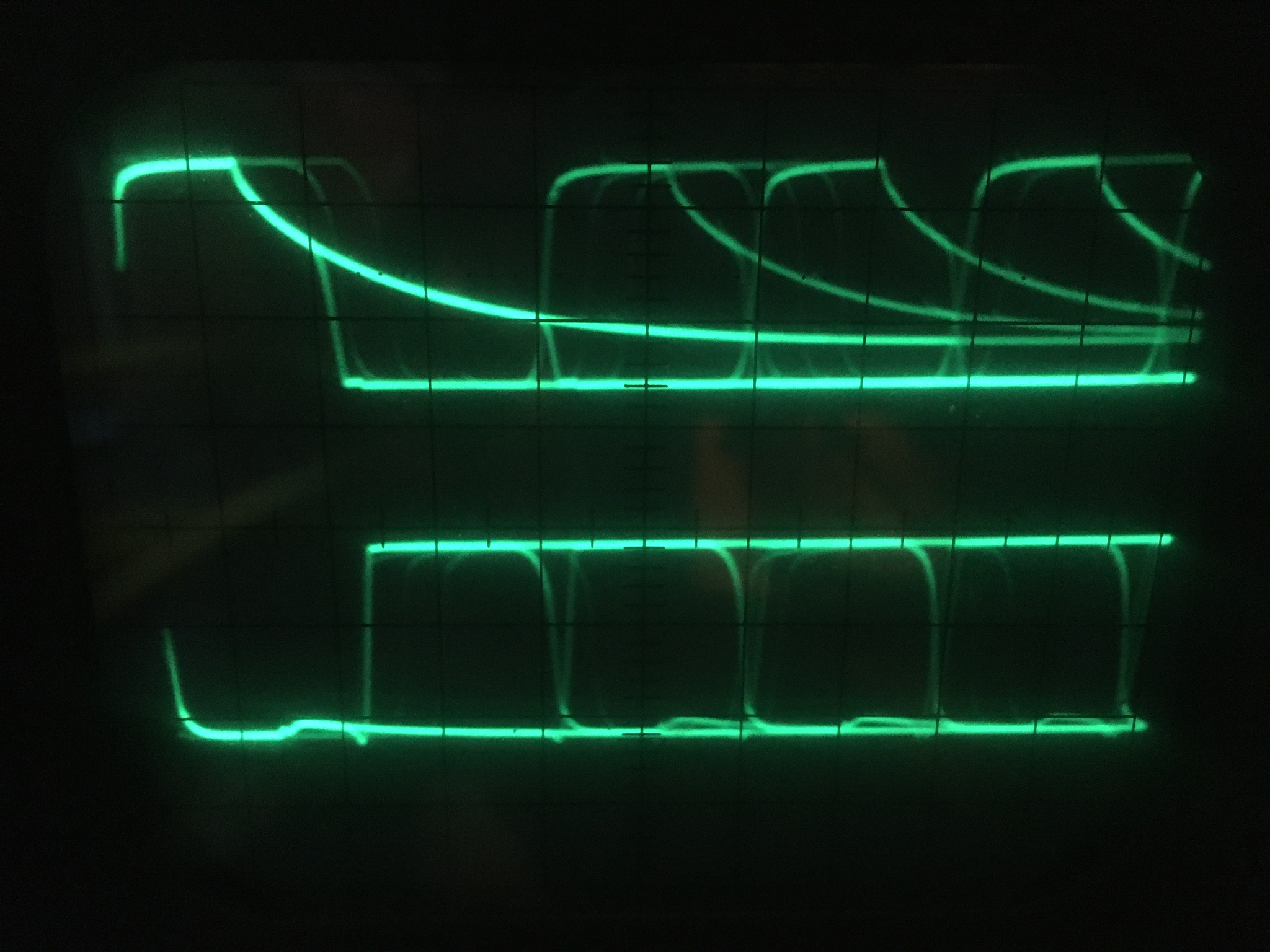
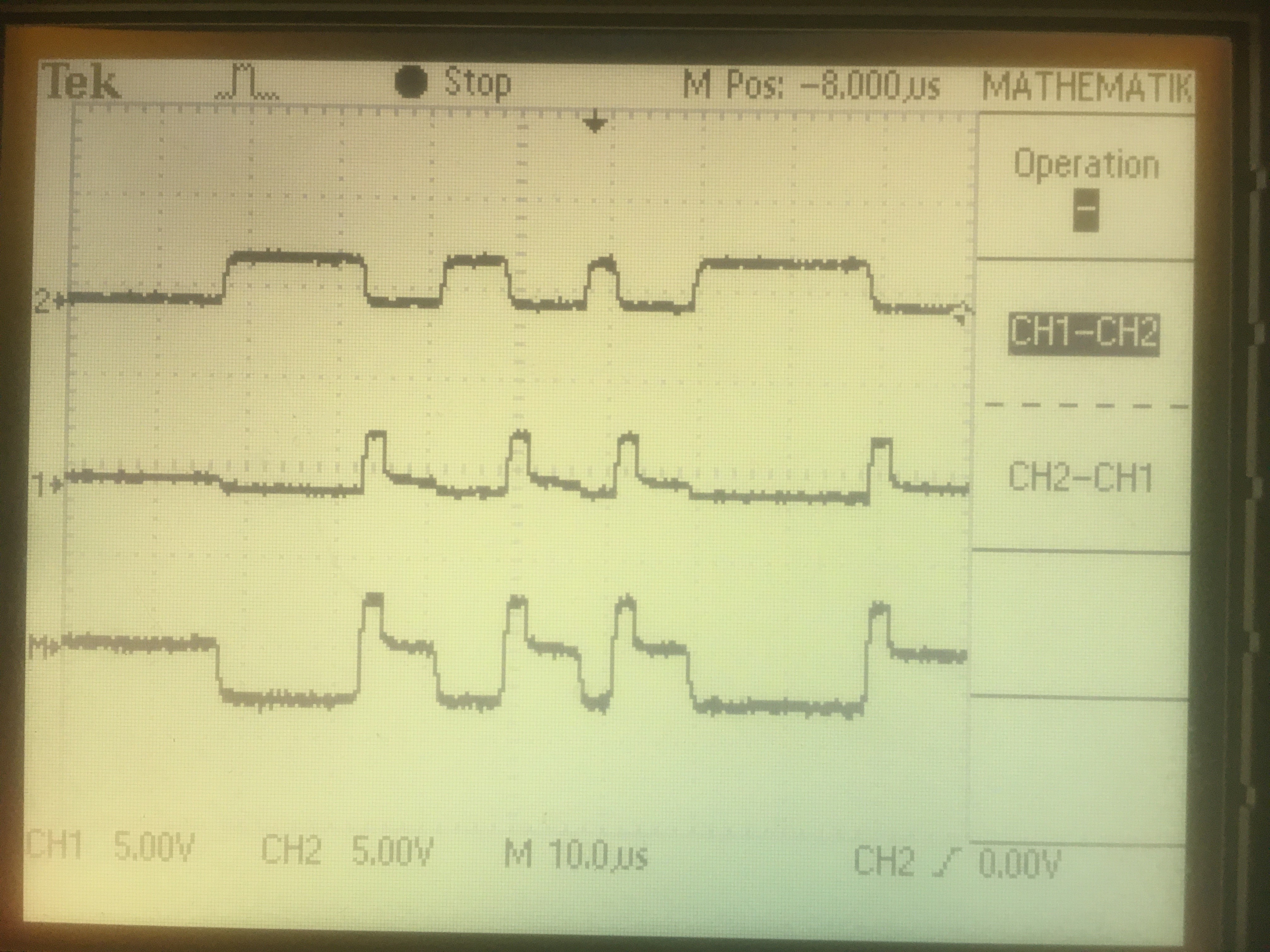
I've now measured the VE.Bus-Signal on Pin 4 and 5 on all my Multis. No other VE.Bus Cables attached. One Multi differs significantly from the others.

Two are looking like the undermost Photograph,

the third is shown in the topmost picture.
1 is pin 4 of the VE.Bus, 2 is Pin 5, Gnd of the Oszilloscope is connected to pin 3 of VE.Bus.

The Signal is much weaker.

I cut all Multis from AC and DC and measured the resistance between Pin 4 and 3; and tehn between 5 and three.

On the to Multis with the better Oszillogram it was 14 KiloOhms, on the Multi with the bad Oszillogram it was 15 KiloOhms on between 4 to 3 and only 76Ohms (no kilo!!!) between 5 to three. All measurements done with Minus of the Multimeter on Ground.

That can't be right. Still my "Service Team" want's me to send all three Multis. And I doubt they will measure the Signal-Quality of the VE.Bus. Problem is: The suspicius Multi works well alone with the Octo and so wth only one VE.Bus Partner, but with the two other Multis in a three Phase-System the VE.Bus errors are showing up. It's typical when Signal is degrading on such a Bus system I'm working for thirty years now. ..

vebus-wechselrichter-phase-3-allein.jpg

vebus-wechselrichter-phase-1allein.jpg


2 |3000

Up to 8 attachments (including images) can be used with a maximum of 190.8 MiB each and 286.6 MiB total.

Related Resources