question

andyalford avatar image
andyalford asked

REC Active BMS for Victron GX - How many contactors ?

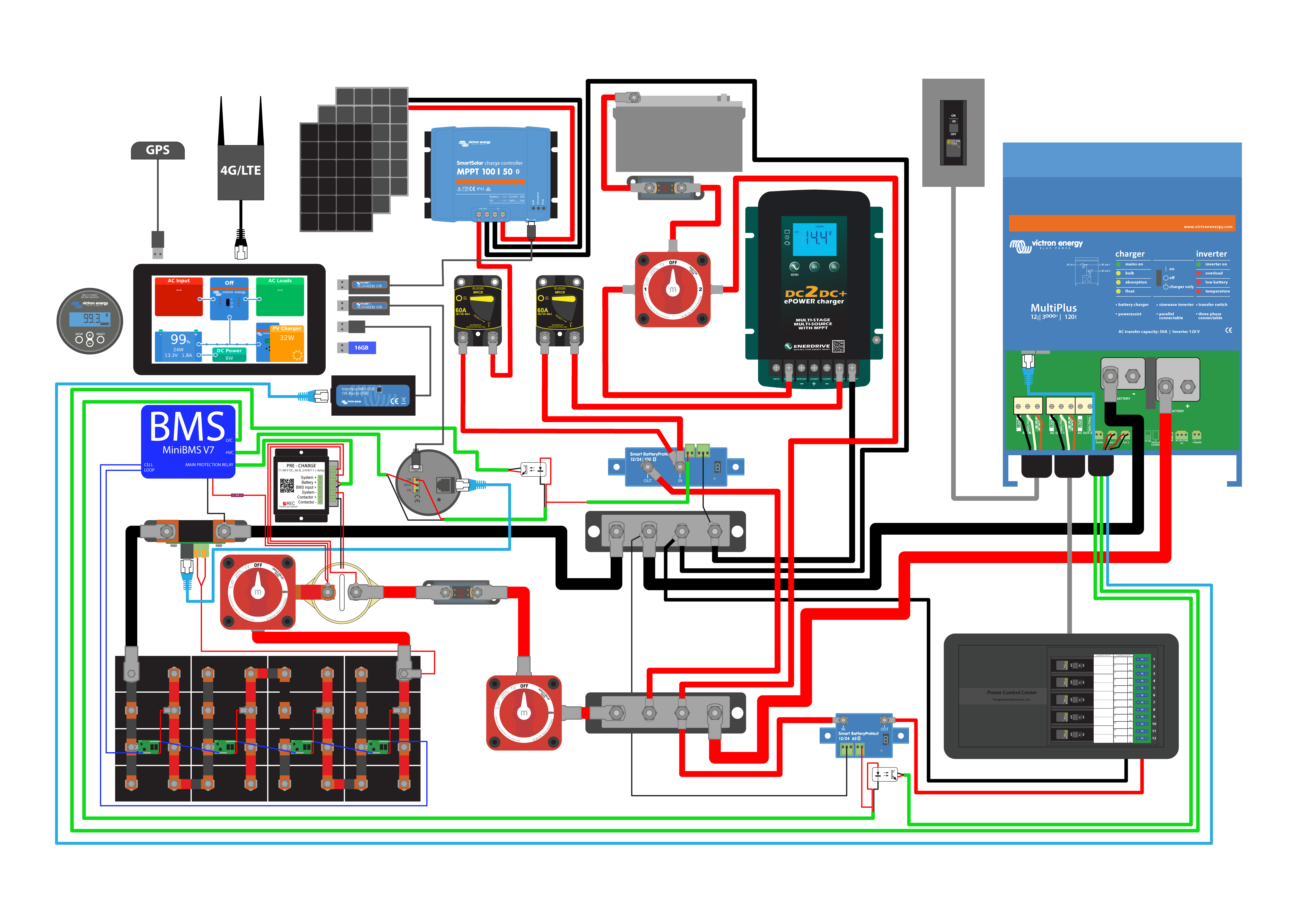
This new version of "REC-ABMS for Victron CCGX" communicates with a GX Device using CAN. It sends Max Charge Current & Voltage and Max Discharge Current along with Battery Voltage, Temp & SOC. The GX Device uses DVCC & SVS to control all Inverter / Charger & MPPT Solar controllers to comply with the charging / discharging limits. Ok, so that sounds good, huh? But I also want to have contactors set to voltage levels in case the CAN bus goes down.

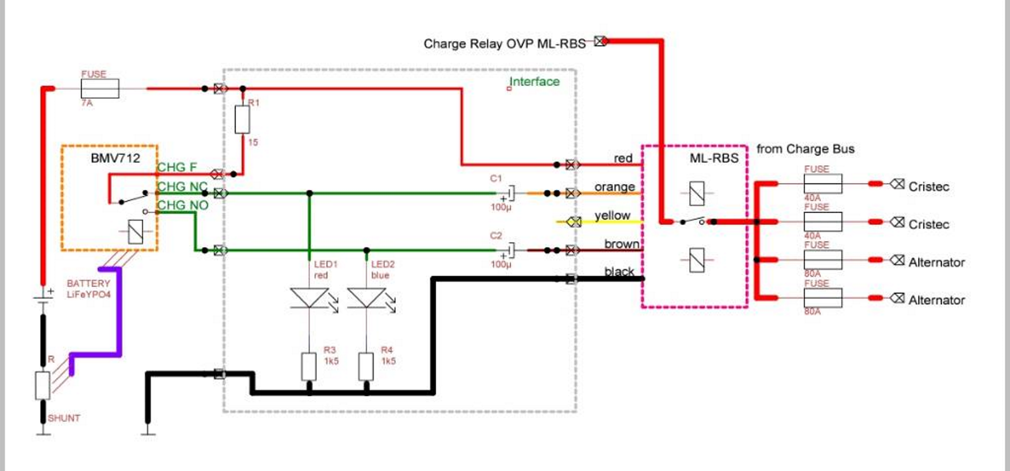
The previous version of the BMS suggested just the traditional two contactors - HVD & LVD to provide High Voltage Disconnect of the charge bus and Low Voltage Disconnect of the DC load bus.

But this version offers a Main Contactor for both HVD & LVD for Victron inverter / charger devices. And another Contactor expected to be used for HVD on non-Victron Charging sources. And though it is not shown in this diagram, I am sure they expected a third contactor for LVD to disconnect DC Loads.

Is this genius or overkill?

I questioned the new functionality, and the manufacturer offered to disable it to make it functionally equivalent to the old version. But I am an Engineer, so I tend to think "here is a Solution, now lets go find a Problem..."

Any thoughts appreciated.....

Andy

----

P.S. And....

I was expecting the fail-safe MultiPlus Inverter/Charger control to be made with a Charge Control signal to AUX1 and Discharge Control to T1 with the Assistant loaded "Two wire BMS (016A)"...

But they are suggesting Charge Control using the Assistant "Input Current Limit Control (0142)" and the AUX1 signal. And programming the Inverter's DC Input Low Shutdown voltage for Discharge Control.

Some REC users I have enjoyed reading before: @paulb @drmi @Boekel @Poppycock @Hakon Ingvaldsen @Eirik @Ceri.w

Lithium BatteryVenus OSBMSCCGX Color Controlgx device
1565705097669.png (78.4 KiB)
2 comments
2 |3000

Up to 8 attachments (including images) can be used with a maximum of 190.8 MiB each and 286.6 MiB total.

kai avatar image kai ♦ commented ·

I don't know the price point or the specifics of the BMS, but ignoring that I'd rather have more options to manage sources & loads rather than less. If my BMS allowed it, I would have configured independent cut outs @ different conditions for charge, load (and possibly even different loads), bidirectional devices and a last ditch master cutout, to provide some semblance of graceful degradation.

0 Likes 0 ·
andyalford avatar image andyalford kai ♦ commented ·

BMS is on the higher end, $500 for IP67 module with nice wiring loom and either Touch LCD or Bluetooth. I will also be interfacing mine to Raspberry Pi and the amazing Venus OS to try out some data logging, Signal K, etc.

Yes - the BMS offers 4 outputs - 2x Relays 2x Optocouplers. Two of these are controlled by the Charge / Discharge Algorithm, Coulomb counting and Cell Voltage sensing. The other two can be set to trigger at a top or bottom disconnect cell voltage.

My ML-RBS 7700 contactors are bi-stable so power consumption is not a concern; and are bidirectional so could work as Main Battery Isolator / MultiPlus disconnect.

@nebulight is suggesting an isolated SBP for the DC Loads, which I think is a nice independent fail-safe.

I like the sound of "some semblance of graceful degradation" - I am an aging Englishman on a 30 year old sailing boat, so I understand that!

0 Likes 0 ·
3 Answers
nebulight avatar image
nebulight answered ·

I personally wouldn't have a contactor on both the high end and low end as they are Normally open contactors and draw power just sitting. If I had a rec BMS, I'd have one main contactor for all failure conditions should there be a CAN failure(HVC, LVC, TEMP, Ect) conditions, and use a BP65 for my DC loads. Since lifepo4 can tolerate overcharge better than it can overdischarge, that's why I'd have a dedicated BP65 just for the DC loads as you don't want that killer the battery when unattended.

For the inverter/charger I also would have thought they would have done the two wire BMS assistant. For me, that's how I do it with my BMS as the low shutdown for voltage discharge doesn't account for individual cell voltages.

7 comments
2 |3000

Up to 8 attachments (including images) can be used with a maximum of 190.8 MiB each and 286.6 MiB total.

andyalford avatar image andyalford commented ·

Thanks for the feedback @nebulight. It helps to discuss these things! I try to talk it through with the girlfriend, but not always so helpful!

I am using ML-RBS 7700 contactor, so power consumption only on transitions (as I understand it.)

I was also considering making the Main contactor, as a complete Battery isolation driven by the REC-BMS, rather than the traditional Load Bus / Charge Bus style. I suppose that is emulating the equivalent of a drop-in battery. Where the battery can be considered a self-contained unit.

Of course, I would put an isolation diode to my Engine Battery to give some kind of control over charging loads, and give a current sink for the Alternator.

And I also like the idea of Smart Battery Protect SBP to the DC Loads, as this is completely isolated system, and can protect Battery and Loads in the event of something failing...

I will sketch out a schematic, as I don't feel I have explained this very well. Picture = 1000 words....

0 Likes 0 ·
nebulight avatar image nebulight andyalford commented ·

Do you already have this setup working with a REC-BMS? Since the ML-RBS 7700 is a momentary switch, it requires a pulse to open and separate pulse to close on a different wire. Not sure if the REC can handle that or not as all examples use a normally open EV200 relay/contactor. In order to keep this open, it supplies a steady 12v to the contactor. Even if you can, those 7700s can draw up to 7 amps when switching which I'm not sure the REC could handle.

Having a main contactor for protection is a good idea in case of CANBus failure, I would still recommend have separate low and high cut offs. As you said, this would function like a tradition drop in replacement, which you'd be losing out on the benefits of separate control (ability to charge when the battery is low and the ability to discharge when the battery is high). My system is different than REC, but I have 4 levels of protection:

1 BP100 installed in reverse connected to the output of DC/DC charger from the starting battery and the output of my MPPT controller. This is my High voltage disconnect the charge sources when a cell reaches 3.6v. It reconnects when the cell recovers to 3.45v. There is a 10 second delay to prevent disconnects from going on and off from voltage spikes

1 BP65 from my DC loads to the battery. This will disconnect my DC loads when a cell reaches 2.9v per cell. It recovers when the cell is 3.1v. There is a 10 second delay to prevent disconnects from voltage sag.

1 EV200 main contactor. If both the BPs fail to do their job, the BMS will open the main contactor which will disconnect all loads at either 3.65v or 2.6v. This does not auto recover and requires a reset with the push of a button. In practice, this should never happen as the BPs should prevent the main protection.

Since this only manages the low current stuff, I also have the two wire assistant with my multiplus. The use the same signal from the BMS for my HVC and LVC, but I route them through an optoisolator instead of feeding the direct 12v from the pack. This will shut off the charger at 3.6v and shut off the inverter at 2.9v.

Since I am using a contactor that's connected to the multi, I actually use REC-BMS' precharge box wired to the BMS to precharge the multi before the main contactor closes. This prevents high inrush current. IF you use a contactor I would for sure get one with the BMS.

With REC, you could kind of do the same thing as they have two built in optoisolators and two relays. You can use the optoisolators for the Multiplus and the relays for a main protection circuit, or two BPs and forget the main protection circuit. This is all in case the CANBus fails so you'd have protection with CAN, followed by protection with the multi and BP (for DC circuits), then protection with a main relay.

0 Likes 0 ·
andyalford avatar image andyalford nebulight commented ·

No, I don't have it working yet. But I am copying a bit of circuitry that CatNewBee has had working on his system for 2 years now... basically 100uF inline capacitor charges on the rising edge and holds long enough to latch the ML-RBS (returning to 0V as it discharges through the LED resistor and other parasitic components. This circuit shows the driver being the BMV relay, but it also works the same with the REC-BMS relay outputs. The 15R resistor is effectively a short-circuit protection which would fuse if accidentally shorted.

Yes, I am losing interest in my original idea of a 'Main Isolator' type contactor for the Battery, because as you say I would be "losing out on the benefits of separate control (ability to charge when the battery is low and the ability to discharge when the battery is high.)" So a quick re-design.

I now have a star effect with each charge source / load attached to the battery through a contactor, and I am working through how I could make the programming work at all the right voltage levels. Your suggestions are very helpful. It is confusing how REC have assigned Optocoupler to some signals and relays to others. I want to keep power consumption close to zero at LVD. Just in case, I am not on the boat.

I can't imagine the need for the Precharge circuit. I have the larger MultiPlus 12/3000/120-50 230V inverter/charge. But I will not drive it hard, so I can't imagine that the start current should be too great. Again this is new, so I don't have experience of it in real life yet. Though I still have to commit to the design now, to order the parts. (2 week lead time to get stuff out to the boat in Philippines.)

If I get a Schematic going tonight, I will attach it here.

0 Likes 0 ·
1565774344596.png (863.8 KiB)
andyalford avatar image andyalford nebulight commented ·

@nebulight - took a second to think about this. I guess the Precharge circuit is mostly only required for the inverter / charger. And I am guessing that baby has a big capacitor at it's input, so the inrush current is high regardless of load... ?

0 Likes 0 ·
nebulight avatar image nebulight andyalford commented ·

Yes, it's for power on. If you are going with REC anyway, the precharge box is around $30 I think. It has the ability to set the time delay from 2, 4, 8 and 11 seconds. I'd go with the 11 second delay.

This may not be the optimal diagram, but here is how I have my setup. My BMS is very basic and only has 3 protection circuits that aren't programmable: HVC, LCV and Main protection. I've added the optoisolators for isolation for the two wire BMS assistant since the Multi is an expensive item. I took inspiration from Victrons VW van diagram. I'm using a Raspberry pi instead of a CCGX or Venus GX. I also run my charge signal through the BMV for temp control to prevent charging under freezing since my BMS has no built in temp monitor/control.

0 Likes 0 ·
andyalford avatar image andyalford nebulight commented ·

Thanks for sending that Schematic, certainly worth a 1000 words. Excellent food for thought. How did you do that beautiful graphic - any specific application?

0 Likes 0 ·
nebulight avatar image nebulight andyalford commented ·

I made them from scratch in Adobe Illustrator. A bit overboard, but I wanted a nice, easy to follow document.

0 Likes 0 ·
edvanz avatar image
edvanz answered ·

Have you asked the question to tine@rec-bms.com he is pretty quick in answering

2 comments
2 |3000

Up to 8 attachments (including images) can be used with a maximum of 190.8 MiB each and 286.6 MiB total.

andyalford avatar image andyalford commented ·

Yes, I get a prompt reply but the replies don't move me closer to an understanding. Maybe it is a language translation thing.

I don't want to be a burden to them, as I know it is the developers answering tech support questions, and they are working on new and much more exciting projects!

Once the unit arrives, I will be able to experiment, and report back my findings to the benefit of the community, without draining their limited resources.

I have ordered a bag of parts anyway, so can try a number of configurations.

Thanks, Andy

0 Likes 0 ·
edvanz avatar image edvanz andyalford commented ·

Hi Andy,


It is a small company and the main developer and owner are the same person.I have a ABMS for 5 year now and still get support within max a day on all my questions. Language can be a small issue, so questions should be asked in the most simple way but still with all relevant info. For my new boat under construction I have a master 9M and slave Q series setup waiting to be installed with the next 2 months. Please keep us updated and I will do the same

0 Likes 0 ·
brets avatar image
brets answered ·

I am running 2 contactors on my REC Active BMS. The main contactor is for my Inverter/charger, Orion DC-DC, and will be for my SCCs once I have them. The second contactor is for all of my DC loads in my camper. All of the Victron loads are controlled by the REC inputs via canbus/Cerbo, so theoretically, the main contactor should never open on a parameter unless the canbus fails. The main contactor also has a precharge on it to charge the MP capacitors. The operation of the system in this manner is so simple! I leave everything on (Multiplus, Cerbo, and main disconnect), and flip the switch on the REC BMS to start the system. The precharge occurs, and everything boots up automatically. When I am going to leave the camper stored for some time, I just flip the REC switch, and everything shuts down. Love the protection and simplicity of it all!20210606-145457.jpg


2 |3000

Up to 8 attachments (including images) can be used with a maximum of 190.8 MiB each and 286.6 MiB total.

Related Resources

CCGX Product Manual

CCGX Product page

Additional resources still need to be added for this topic

Battery Compatibility

Did You Know - How to create a battery profile for non-Victron batteries?

Victron Venus OS Open Source intro page

Venus OS GitHub (please do not post to this)

Additional resources still need to be added for this topic