I'm setting up my multiplus compact to work with my Renogy lithium phosphate batteries. When I select the battery tipe of battery to lithium is telling me that I need Assistant. What is that? Which one do I use?
asked
What assistant to use to setup Renogy Lithium Battery?
Renogy is not a battery that has been tested and approved by Victron:
https://www.victronenergy.com/live/battery_compatibility:start
You will need to contact your battery supplier or Renogy themselves and see if they have a recommended configuration when using Victron Equipment.
Others in the community may also have information or experience. Some prior questions and answers about Renogy are here.
Matthijs addressed that question here:
I don’t see the word Victron anywhere in the linked thread. But since they are the second largest selling brand for solar RV installations in the US I am assuming they failed the testing process?
That’s not a great assumption, Victron as a company is based in Europe (The Netherlands to be exact). Renogy isn’t available directly in Europe at this time as far as I know.
They might be the second largest USA RV solar panel brand (I use them myself), but they are most definitely not the second largest lithium battery on the market.
Fair enough. I was looking at their brand in general and did not break it down by share of the battery market. But they are still a major player and it seems like a significant oversight to ignore that.
There are hundreds if not thousands of small companies trying to make it in the drop-in lithium battery space. It is a ton of work to certify one of them, and each new BMS design they come out with could trigger rework. It's unrealistic (and economically infeasible) to do all of that with more than a handful of vendors.
The good news is that most of these batteries work similarly and the Victron equipment is pretty configurable. You just have to do some of the work yourself.
Happy to do the work myself. But I'm not as smart as the EE's that know this stuff.
For example, here are the Renogy specs: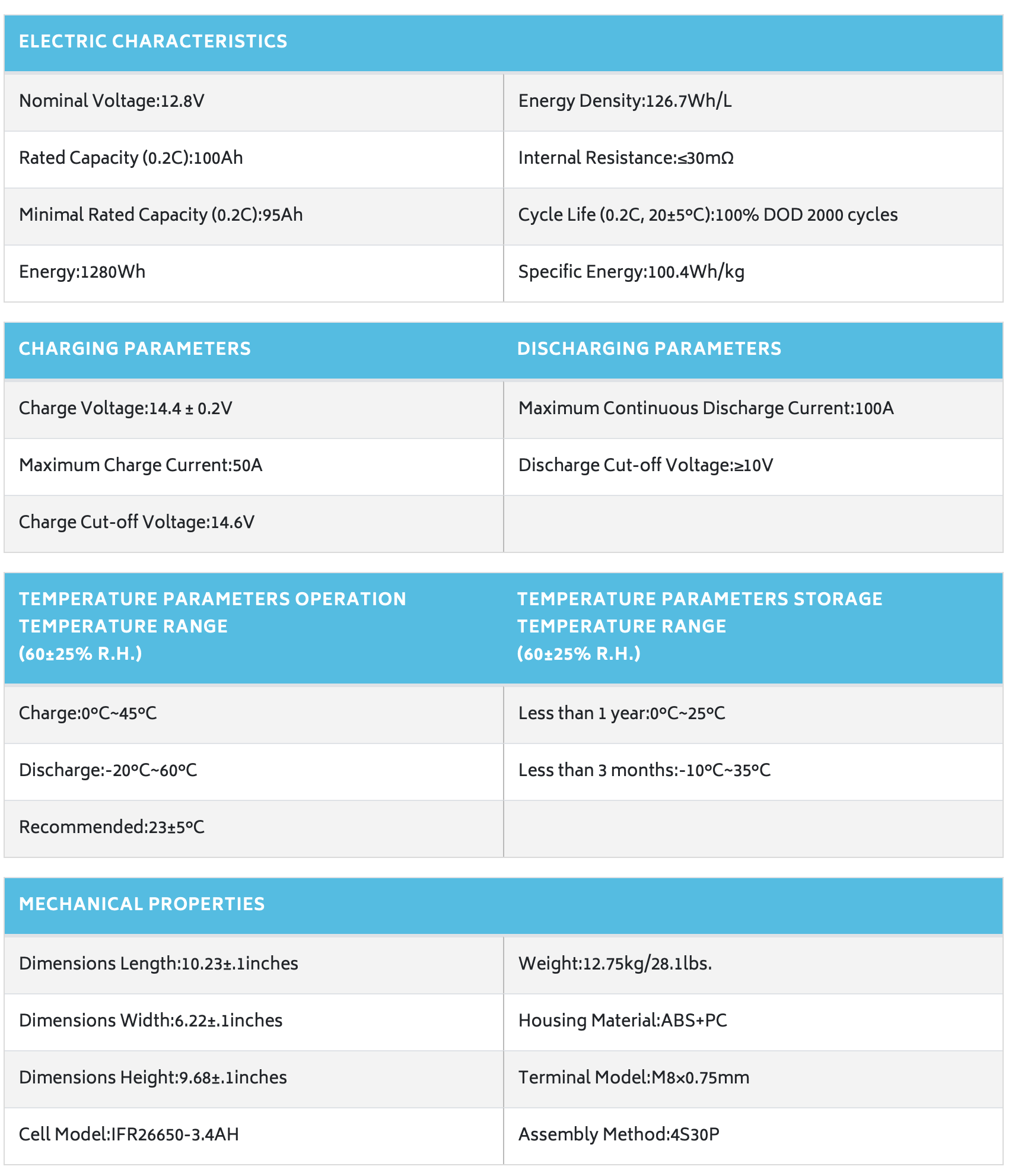
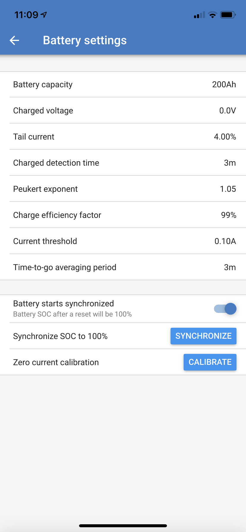
And here is what I think that means for the Victron battery monitor (using 2 100Ah lithium batteries from Renogy):

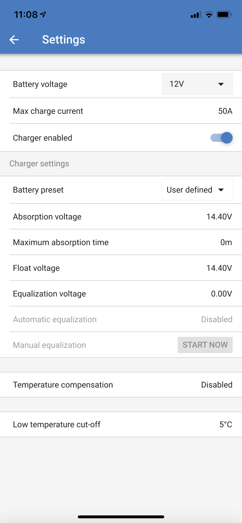
And here is what I think the solar charge controller should look like:

But not being an EE, I have to make educated guesses at how to translate the specs on the Renogy battery document into the settings in the Victron products.
So maybe there is a middle ground. If certification is too onerous, perhaps advice regarding "if the specs say this then the settings should be this" would be a great piece of customer service...
Good suggestion. But no inverter-charger vendor does that to my knowledge... so it would be a first!
One thing you can do is read up on other’s settings, here and elsewhere.
Another option is to ask Renogy for their advice. (good luck)
Finally, you could contribute your “answers” here and maybe pay it forward.
Some of the settings are pretty much personal preference, with trade offs each way. There may not be one true answer. But I do think a set of templates or guide would be nice to have. (It’s not really that complicated.)
14.4v is way too high as a float voltage!!! You will kill the batteries if they get that voltage after they’re full. Reduce that to 13.5v as per the victron default lithium settings.
14.4 is perfect as absorbtion voltage,

Thanks for this. It’s kind of crazy but that was the Renogy suggestion. I’ll dial it back because I’m sure if I kill the batteries that way they won’t consider it a warranty issue.
Thanks though I am still not sure what you mean. Renogy wants no float voltage at all.
But until Victron makes that an option (please Victron, add this option and also a pin option to lock out equalization) then at Renogy engineering their belief appears to be that to cancel out this shortcoming from victron, setting float to 14.4 achieves the same thing.
I guess your link suggests the engineers at Renogy are wrong?
That Being said, my AC charger, optimized for lithium but not adjustable, is set to the following parameters.....
Would be great to see Victron pick one up. This will influence how I build out the rest of my monitoring, converting, controlling aspects of my system.
Finally I think I have the multiplus set up to work with the Renogy battery. If I use the charging parameters recommended by Renogy the multiplus doesn't ask for assistants. Hopefully I did wrigth.
You do not need "tested" lithium batteries, or a special assistant. I am using 12x 960Wh DIY lithium battery modules built from 18650 cells, which works beautifully with my split-phase ESS, without a "Lithium Battery Assistant" installed on any Multi in my setup.
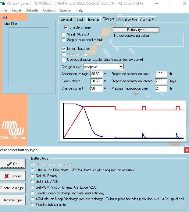
You do however at least need some basic knowledge about the battery you are planning on using, such as the chemistry, and number of cells. Here is how I have my charger profile configured, as you can see, I do not currently have a specific "battery type" selected, what I did was start by selecting the LifePO4 Lithium option, which did tell me I need an assistant installed (for communicating with the BMS, which I ignored), then I just customized the voltages for my particular battery. As soon as you start customizing the options, the "battery type" is automatically set to "no default" which is still just fine for Lithium batteries. Do leave the "lithium batteries" box checked, this alters the charging curve slightly.
The purpose of a lithium battery "assistant" is so the MultiPlus can communicate with the Battery Management System on your battery pack, if in the event that one individual cell in the pack goes over voltage, the idea is the BMS would then be able to tell the MultiPlus to stop charging. If you are using "incompatible" lithium batteries as I am, you should take care to ensure that the "absorption voltage" is set lower than the sum of the max cell voltages of your pack. For example, my battery is 7S NMC, each cell has a maximum recommended charging voltage of 4.2v, multiply that by 7, and you now have the maximum "pack" voltage, which is 29.4. To avoid any issues (and also prolong the battery life), my MultiPlus is set with a max absorb voltage of 28.6, divide that by 7, and you will find that the individual cells cease being charged when they reach around 4.1V. If for some reason one modual becomes imbalanced, and one of the 7 cells does reach the 4.2v cutoff, the BMS will shutdown that module, preventing the MultiPlus from charging it further. If too many modules shutdown, the overall DC voltage will rise when the MultiPlus tries to feed in additional current, and it will eventually stop charging altogether this way. Conversely, your low voltage cutoff should be set higher than the sum of the individual cells' low voltage cutoffs to avoid the same issue at the low end.
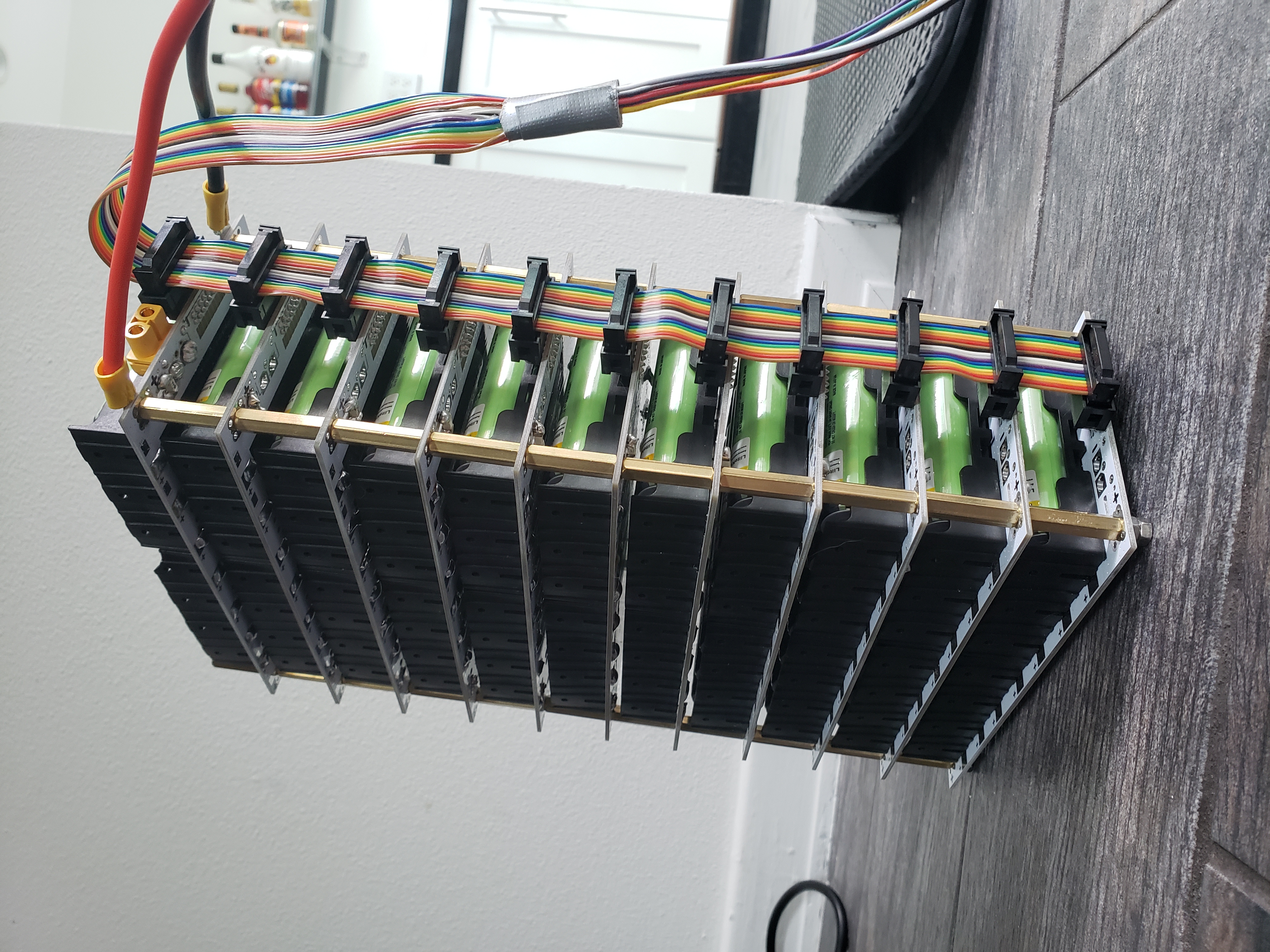
@ee21 is your battery pack constructed with Jehu Garcia's PCBs? Do you use his BmS as well? I like the system but boy does it seem expensive. I have a Tesla module I would like to disassemble to make a 7s pack.
Tom
Please do not use these 'Jehu' pcb's for anything else than a test-setup.
There are serious design flaws in it that can leave part of the pack unprotected by the bms, and / or have big current flowing through through the balance cable.
The 6s Tesla modules are perfectly usable as is, as long as a suitable, well configured, bms is used with it.
Thank you for the comment. Of course the PCB concept is an interesting one, but I think it is still quite expensive and I worry about the plastic battery holders melting if you should place too much current pull from the battery.
Yes my Tesla modules are well constructed with metal buss bars, individualy fused and heating and cooling pluming. Still I wish it was a 7s module. I do have a three low voltage disconnects protections and two over voltage disconnect protections and cell balancing engineered into my system plus liquid module heating for low temp charging.
I do have a damaged Tesla module with a handful of blown wife fuses I am trying to figure out what to do with so I was just trying to figure out what to do with it or use it. I understand they are most difficult to test apart to get individual cells.
Tom
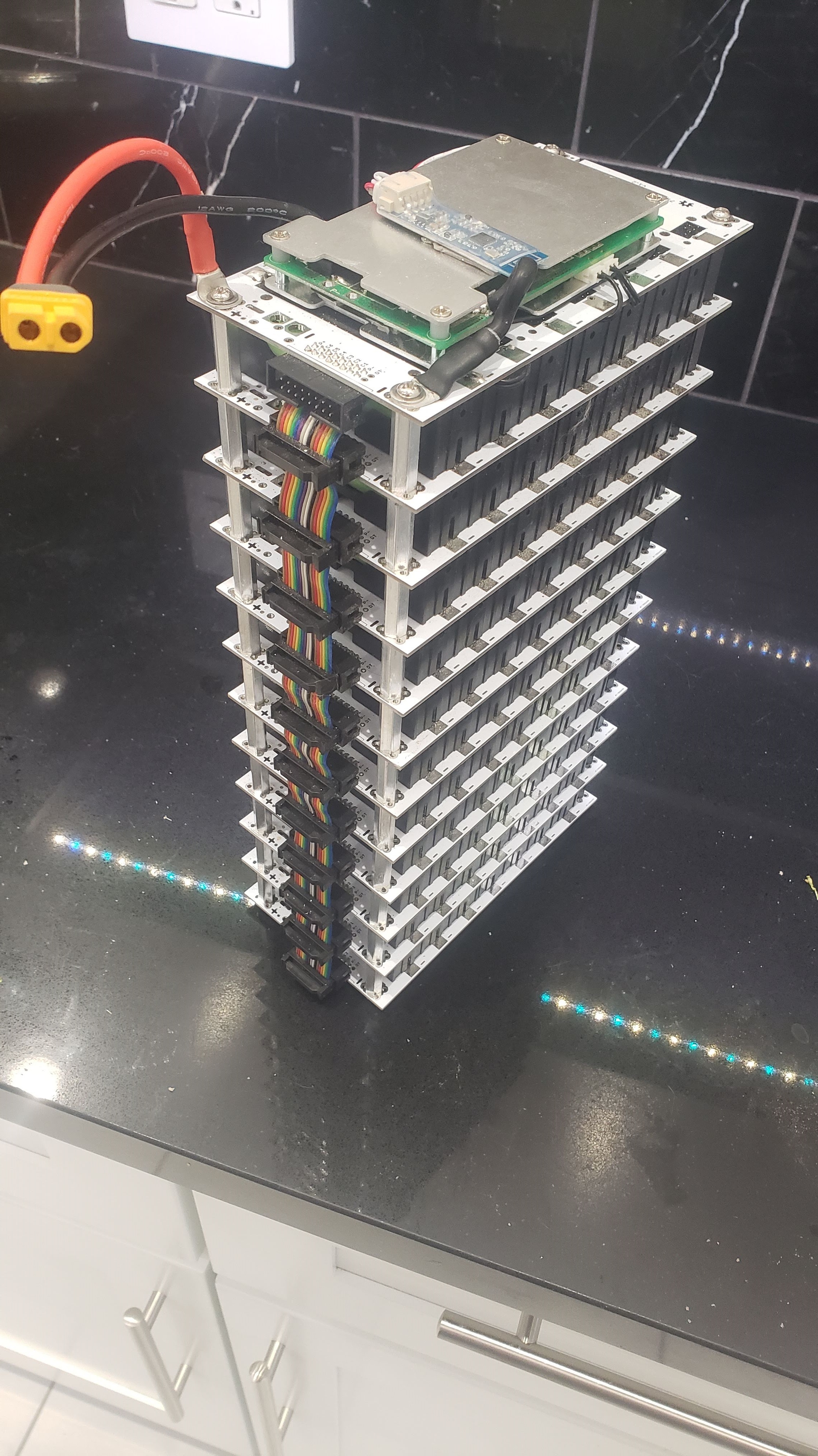
@Tom Yes that one is Jehus PCB, that is a photo of my "prototype" module, which I have since improved upon myself. The initial build was indeed very expensive for 132 boards, a large number of which were initially failures due to user error (think I ordered supplies for 200), but the idea being that in however many years it takes the cells to wear out, the boards will hopefully be reusable, and the cells can be exchanged quickly, and with very cheap replacements. Using 3400MAH cells, 7 per board * 132, I have about 11.6KwH of total battery capacity, which I have a self-imposed limit of 80% usable capacity. After I completed the project, I costed everything, including the failed components, which totaled around $4,000 USD. To simply replace the 924 cells going forward will only cost around $2,300 with the current prices from the same seller however. Considering 11.6KwH worth of other brand-name lithium battery storage would likely cost around $8,000 USD or more during the initial purchase, and again and again when it needs replacement, I think I came out pretty well ahead. Regarding heat, yes indeed, Jehu tested the boards and confirmed they are rated for a maximum of 2A continuous. Multiply that by 132, and my maximum current draw is around 260A * 24v and you have a rated continuous output power of around 6.2KW. These boards are not "power" boards, they are intended for power-walls, where you are looking at C/2 > loads/charging. I am using two MultiPlus Compact 24/2000 in Split-Phase, which would overload if I tried to pull more than 3.2KW for very long anyway. And lastly, regarding the BMS, I am not using Jehus, I did not like the design. I am using a custom Bluetooth enabled BMS, one per module for a total of 12 BMS boards, they are each rated for 60A continuous, but have been configured with a 15A over-current shutoff which will cut the connection if exceeded, keeping the current well below 2A per board. I have kept a close eye on temperatures and cell voltages etc during the initial months after completing and installing the battery modules. In one case @Daniël Boekel (Victron Energy Staff) I did observe significant heating of one of the module's balance cables, which after pulling it apart and testing, found was due to the primary fuse on several boards blown, but the balance fuses intact, which essentially meant the discharging/charging was flowing through only the balance leads to the other boards with good fuses. I fixed this by bypassing the board level fuses, and fusing instead at the pack level. This does not fix the other problem you mentioned which when the balance fuses are blown then leaves that board unprotected by the BMS to some extent, or more specifically unbalanced at least. If I were to go back and do this all again, I probably would not choose Jehu's PCBs again for the aforementioned issues stated.
Wow is all I have to say. You have invested lots of money and time. I think the PCB idea is very interesting for the hobbyists, but I wanted a 24 volt 7s battery your size for my RV and one Multiplus 24/3000. I just could not justify the cost over just using my 2x 5.2kwatt hour Tesla cells and just loose some of the output with a 6s design. I have tried to contact Jehu but never got a reply. I have one Tesla module that has about 24 fuse wires blown thinking I could year the module down for the cells as all the 18650 cells are still good. Now I will not go the way of the Jehu PCB.
Do you have a recommendation for a good BMS to be used with standard 6s Tesla modules? My findings is the REC 16 BMS would be the best, but at $1000 I am not sure I want to put out that much cash.
Tom
Didn't the latest VE Bus firmware lower the minimum cut-off voltage to address this issue with the 6S packs in particular? I would look into upgrading to the 460 firmware if you're still having an issue getting 100% out of your pack, although for life cycle purposes you probably would want to avoid a full discharge cycle anyway. But yeah, if you already have an "assembled" 18650 pack, even if some of the cells are toast, you're probably better off sticking with it. You could always test those individual cells and refuse if they are good still..
Regarding BMS, my needs are a little different, since each of my "packs" is only 960Wh, a smaller BMS works fine. I used a 60A Bluetooth-Enabled BMS from AliExpress, they are pretty generic, along with the USB-PC module can be extensively customized by the end-user. While obviously anything from China can be suspect, I did run a number of tests to confirm they are doing the job the are intended to, and indeed they do. My only wish was that the balance current was a little higher (I think it's only 0.5A), but they do an excellent job of cutting off either the charge/discharge current (controlled separately) when any of the conditions are met. While you can wire BMS boards in parallel, I personally would try and avoid this, and is one of the primary reasons I avoided Jehus BMS board, along with the lack of Bluetooth connectivity or any ability to either program, or check to make sure the unit is still in working condition.
The sellers who produce these BMS boards are always advertising that they can make you a custom product, and I have seen 150A-200A Bluetooth BMS boards before, but I would advise simply for the fact they are Chinese products, that you size your BMS for no more than 1/2 its maximum rated current.
Final revision of my modules complete with BMS board and 7mm aluminum stand-offs: 