question

Danakil avatar image
Danakil asked

Offgrid - Generator priority over solar

Hi,


On one of our client's site, we have a problem that we cannot solve:

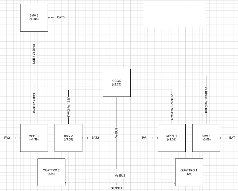
It is composed with:

  • A 15kVA Generator
  • 600 Ah battery bank mounted in 48Vdc system
  • 2 synchronised Quattro 48/5000/70
  • 2 SmartSolar 250/100
  • 3 BMV
  • 1 CCGX


Configuration:

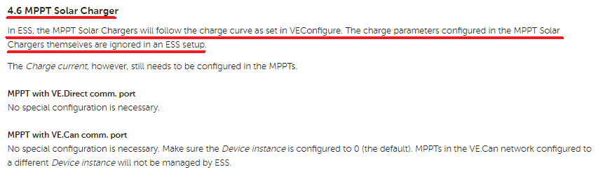
  • Absorption voltage: 57.6Vdc on both Quattro & SmartSolar
  • Floating voltage: 55.2 Vdc on both Quattro & SmartSolar
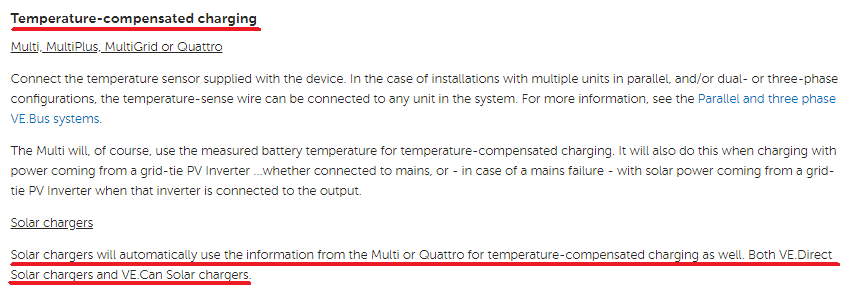
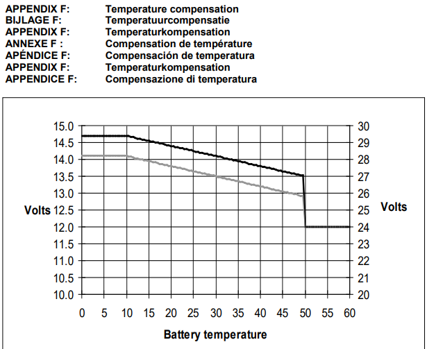
  • Temperature compensation: -120mV/°C on SmartSolar
  • A couples of Generator Start conditions (temperature, voltage, SoC, overload, etc...)


Please find below a synoptic of this system, and take note that one of the SmartSolar is connected to the CCGX with Ve.direct/USB adaptator while the other one has direct Ve.direct connection:


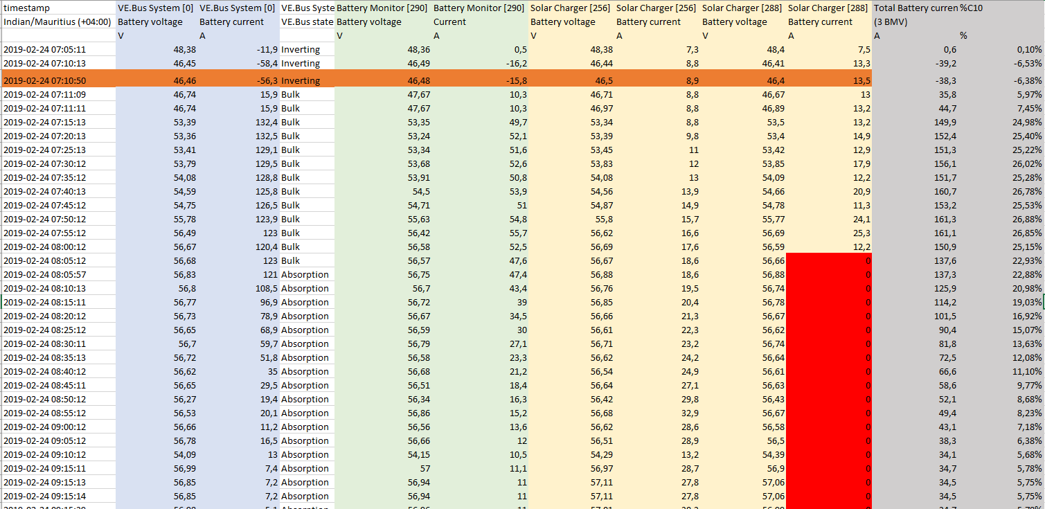
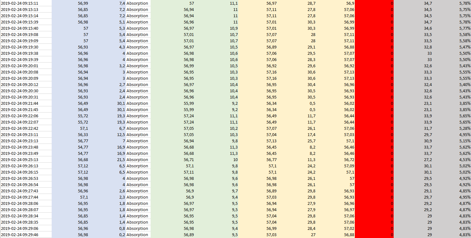
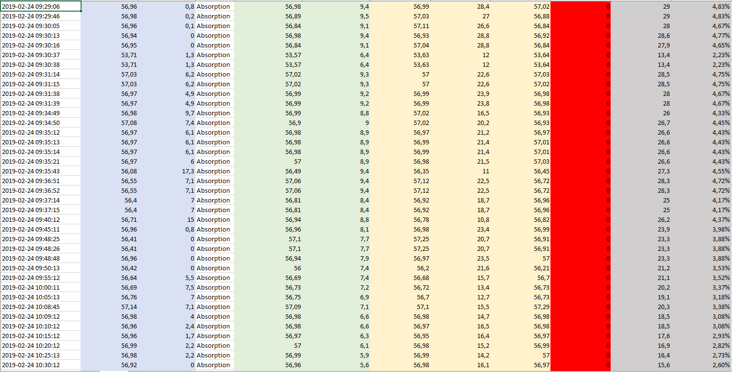
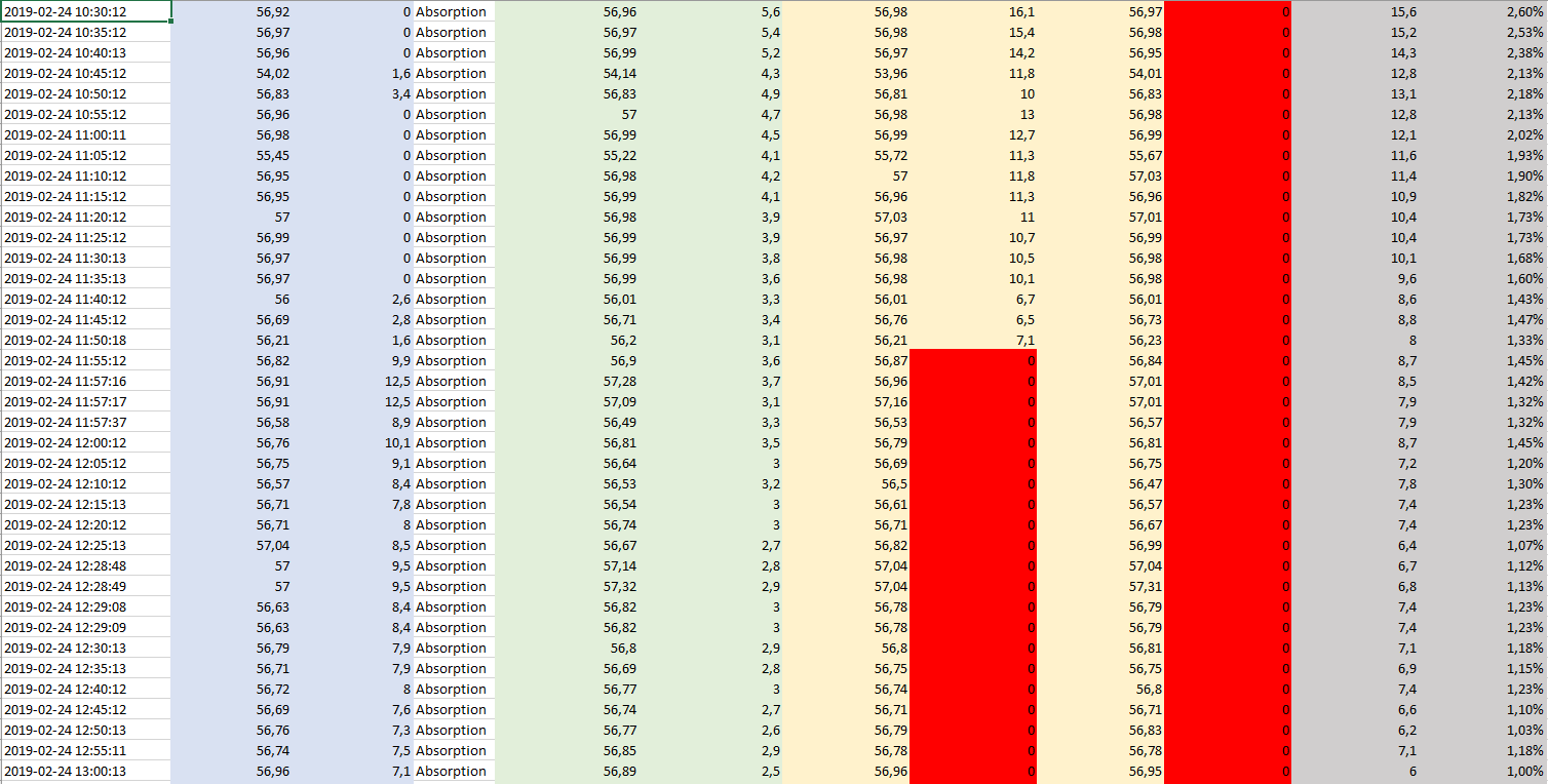
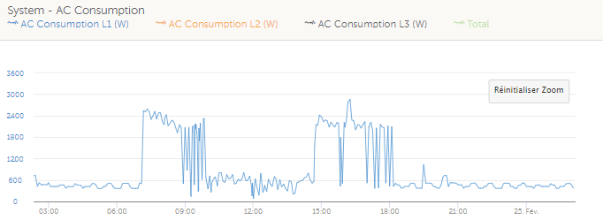
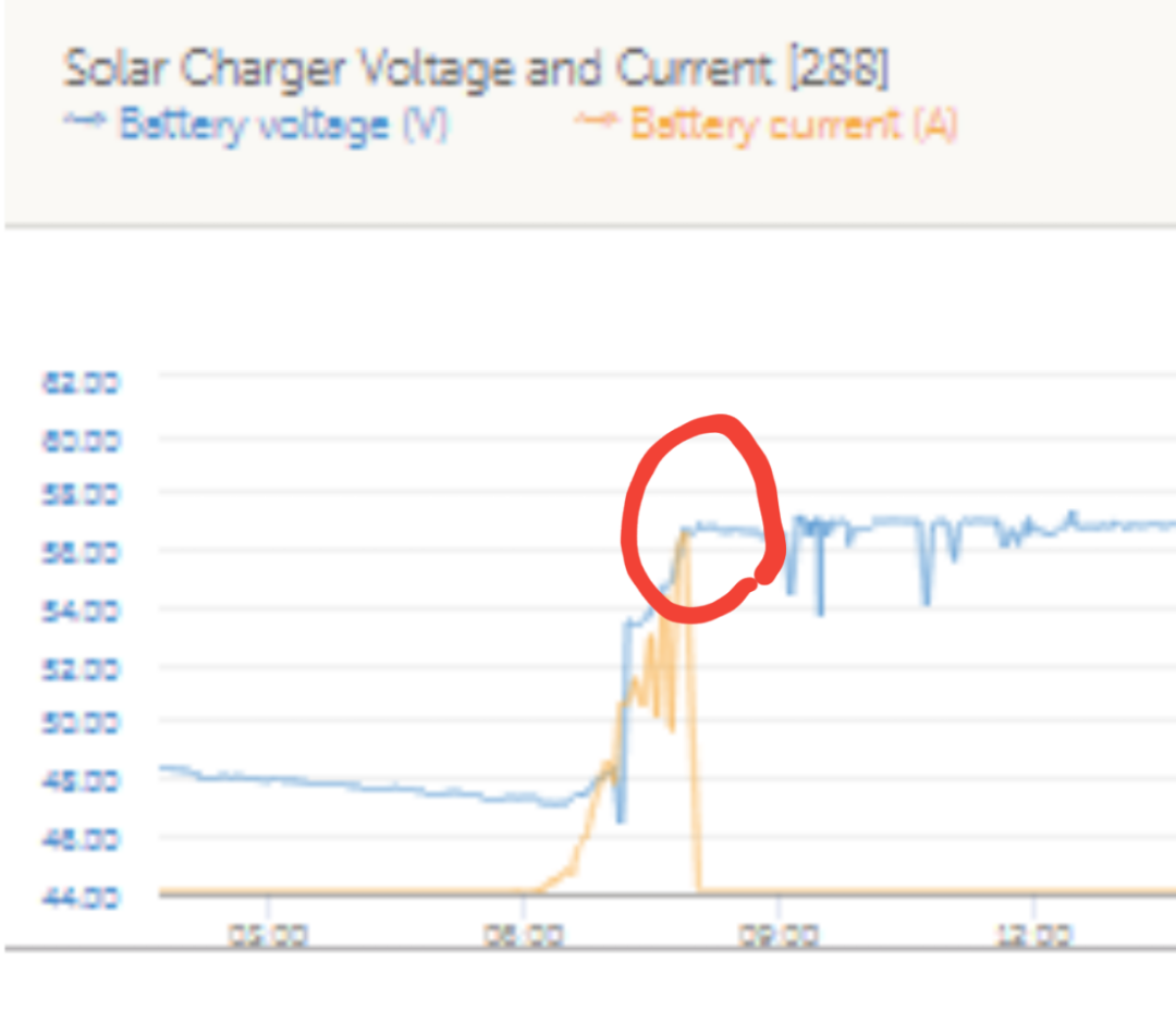
We found out when the generator is ON, and after reaching a certain voltage, below the absorption voltage (for example 56.4Vdc), the solar stops producing.

At first, and because I didn't know yet about the DVCC feature, I tried the old way to prioritize the solar by adding a sligthly different voltage on the SmartSolar (+0.2Vdc => 57.8Vdc @ 25°C instead of 57.6Vdc). It worked pretty fine on the tests bench (1 x Quattro + 1 x SmartSolar) but unfortunately didn't work on the client's site (2 x Quattro + 2 x SmartSolar).

Then, I set-up the DVCC, making sure all the software version were fine, tested it in my office => all good. But then, again, same behaviour in our client's site, the solar is not prioritize (needless to say, the client is not happy).

Finally, I set-up a mixed solution, DVCC and +0.2Vdc on the SmartSolar, it worked a bit better but not enough for the client.

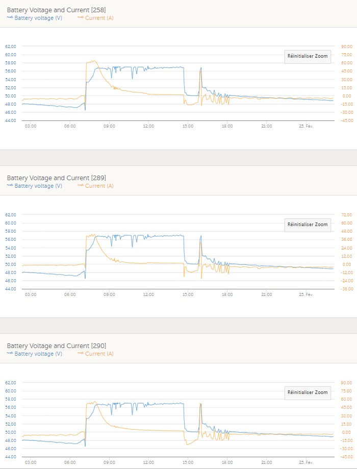
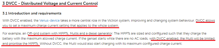
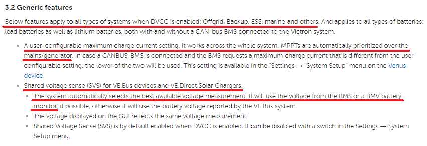
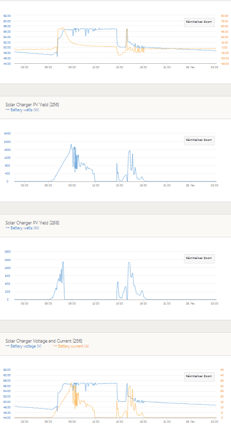
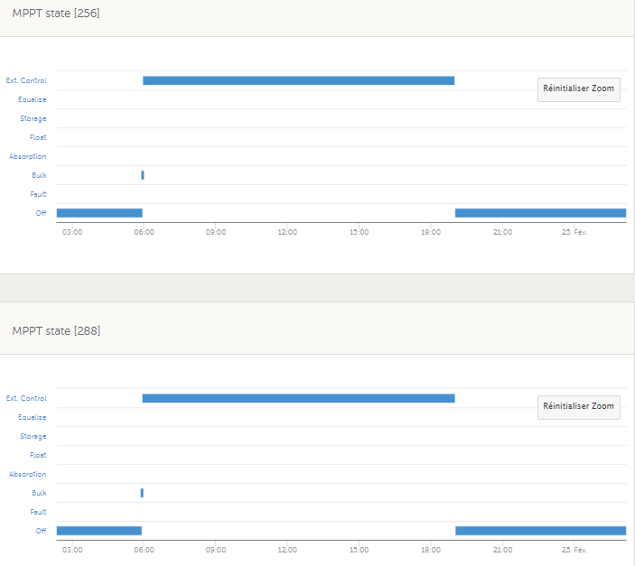
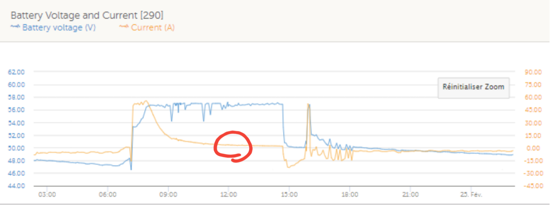
Below, a screenshot of the VRM of yesterday's recharged:

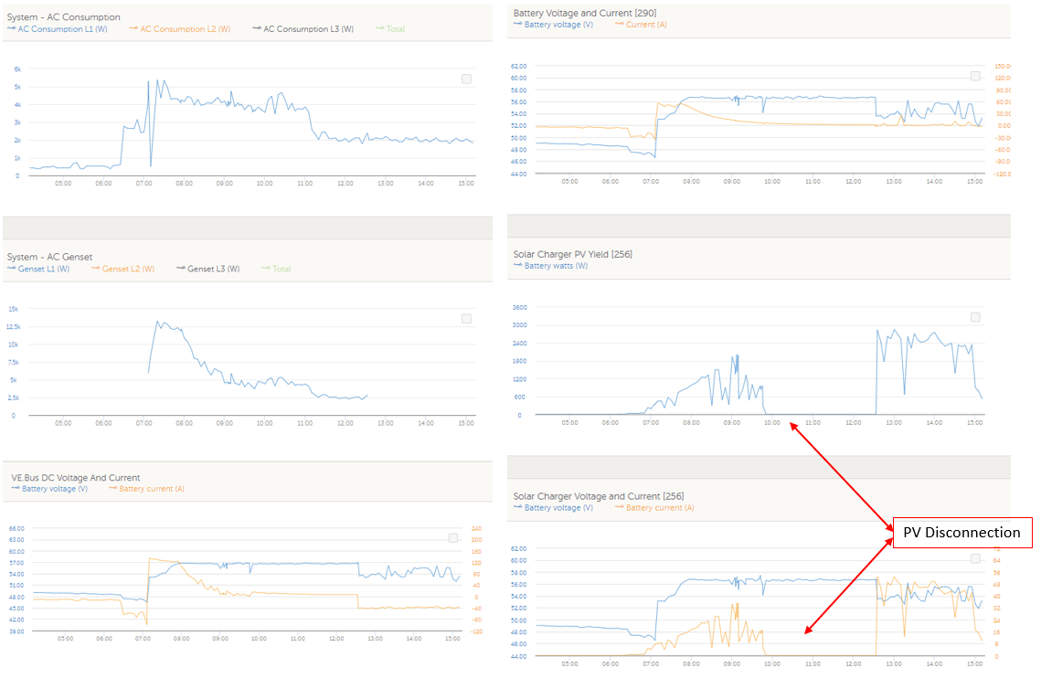
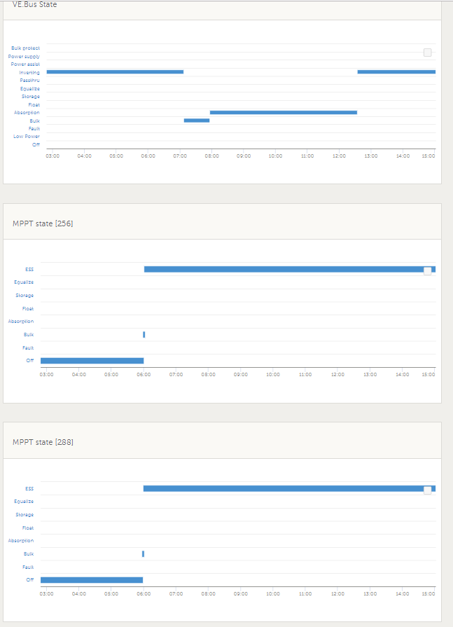
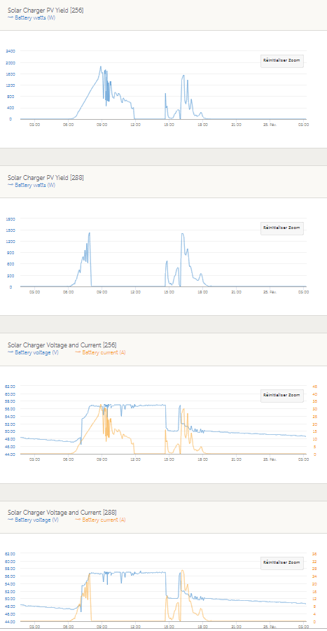
We can see that the SmartSolar [289] gets off after a little while, the 2nd SmartSolar took off an hour before.


So my questions:

  • Do you have any idea of what's going on ?
  • Has DVCC feature been tested with a couples of Quattros and SmartSolar ?
  • Does DVCC work with a SmartSolar connected with Ve.direct/USB while the other one is connected straight on Ve.direct ? Not sure the software can easely do such a thing.
  • On Victron Connect App, the voltage parameters are given for 25°C or 20°C ?
  • Do you think a Smart Battery Sense will fix the problem ? I readed a lot about it (https://community.victronenergy.com/questions/258/dvcc-battery-temperature-sensor.html)
  • Can you confirm me the temperature compensation parameters in a MultiPlus/ Quattro is -5mV/°C or less ?
  • Last, why Victron choose as a default settings to prioritize the AC power over the Solar ?


Thank you a lot in advance.


Best Regards

GeneratorsolarvoltageDVCCtemperature compensation
1552043836338.png (141.4 KiB)
1552043842219.png (141.4 KiB)
1552044549331.png (191.8 KiB)
2 |3000

Up to 8 attachments (including images) can be used with a maximum of 190.8 MiB each and 286.6 MiB total.

6 Answers
JohnC avatar image
JohnC answered ·

Hi Nic (& Erma). It appears to me that that the mppts are dropping into Float mode well before the genny does, so then will back right off. The genny seems to be staying in Absorb for quite a long time, and perhaps could be shut down once that's been reached, or a little later.

The charge algorithms are different between the quattro and mppts, so they won't be following the same purpose. I can see why the genny started with some pre-dawn load on the batts, but really it doesn't have to go on that long. On VRM you should be able to see the status they're targeting.

DVCC mightn't help much (if at all). I'd tend towards leaving the mppts on default settings and working on the quattro charge settings and genny run time so they don't overwhelm the solar.

I suspect it's that simple - but it won't be so simple finding the optimum mix. I use a genny too, and only run it after dark. Maybe with a big planned load coming on in daytime I'd start it manually, but that's rare.

And of course if you could educate your client to diy these tweaks, then you can just delegate the responsibility.. :)


2 comments
2 |3000

Up to 8 attachments (including images) can be used with a maximum of 190.8 MiB each and 286.6 MiB total.

Danakil avatar image Danakil commented ·

Hi JohnC,


Thanks for your reply.

The Generator started on Low Battery voltage for 10 000 seconds to avoid sulphatation and trust me it's not long enough, a 10 to 12 hours long recharge in absorption Mode should actually be done but that's the maximum on Victron product.

The charge algorithm is pretty much the same, IUI step profil (Constant Current / Constant Voltage), my only doubt would be on the temperature compensation profil between the SmartSolar and the Multi/ Quattro.


As asked, please find below the converter's states:


My questions are more about the DVCC algorithm, shared values and communication devices.

I told to the client to set-up a daily start a night to bring the SoC at a good level at sunrise, and complete the charge with solar energy to make it "simple" but he disagrees....


Victron Staff please help !


0 Likes 0 ·
1552051943069.png (33.4 KiB)
1552051948184.png (33.4 KiB)
JohnC avatar image JohnC ♦ commented ·

Hi Nic. I'll bump ya cos you've dropped back a page, and I've more spare time than Victron staffers. :)

The charge algorithms may seem the same, but they're not. I'm not privy to the fine points, and there's reasons for that that I can understand. And a lot of this stuff seems to have risen on the development priority list, but we'll have to wait. Absorption time is where you're seeing issues, and that's where each algorithm differs significantly. Invariably the mppts will drop back to float earlier than the Quattros, and by then with good V in the batts, time to consider shutting down the genny.

But I note your client has opinions, and so do you with 'sulphation' issues. Then there's also Equalization options to deal with that too.

The 'comms' issues you suspect may not be so serious, if they exist at all. KISS principle, Sure it's a biggish system, but the principles are the same as the little guy in an RV - important to him too!

Posted in good faith. And I wish you and your client well.. But keep up the yarn if you will, that's fine by me. :)

0 Likes 0 ·
Mark avatar image
Mark answered ·

I also have a strong interest in this topic - as I just setup a new system yesterday and observed the same behavior occur (Multi 24/3000, SS MPPT 150/85, BMV-712, CCGX, 24v 560Ah Batt Bank).

My initial charge voltage settings were set identical for Multi & MPPT (apart from temperature compensation in the Multi that I cant check or update - another concern of mine)

When I fire up the generator (during bulk phase), as soon as the battery voltage gets close to the absorption voltage the MPPT switches from bulk to absorption & then quickly to float. This would obviously occur because the MPPT reaches the <2A charge current threshold since the Multi seems to be a little 'ahead' & doing all the work - ending the absorption phase.

I have NOT yet had a chance to play with things to improve the behavior of this setup, my next steps were also going to be the work around of manually setting a slightly lower charge voltage set point on the Multi &/or by enabling DVCC.


Is there anything else that I can/should do/try?

Is it expected that enabling SVS (shared voltage sense) would resolve this / help as any small discrepancy in voltage reading should be eliminated? (I think not as that would just provide a common voltage status, but the set point / target voltage for MPPT vs Multi would still be slightly different unless the temperature compensation & temperature reading/source is also 100% identical)

Is there an ESS that would help? (Noting that this is a full off grid setup)


Note: CURRENTLY I also have a 'smart battery sense' bluetooth connected to the MPPT, primarily to provide real time temperature data. I am using this because I have utilized the BMV 2nd input for mid-point measurement & don't want to give it up. This temporary measure was also recommend by Guy Stewart in a question I posted some time ago (despite the fact that I also have a CCGX & BMV in the system).

Once the Multi temperature sensor data is available for distribution via DVCC then I plan to disconnect the smart battery sense & enable full DVCC. (according to the GitHub ticket #374 this seems imminent so I am eagerly awaiting release)

This fact will probably prevent me from enabling full DVCC at the moment...

Regards, Mark.

11 comments
2 |3000

Up to 8 attachments (including images) can be used with a maximum of 190.8 MiB each and 286.6 MiB total.

Danakil avatar image Danakil commented ·

Hi Mark,


Thank you for your feedback and your interested point of view about the current value threshold.

Then, I checked some datas, and it appears that, in my case, it is not about the current reaching a certain value, as we can see below:

The Solar Charger [288] switched off at 11:49 a.m with a 7.1A sent at 56.98Vdc, while the other one ([256]) switched off at 7:57 a.m with a 25.3A and 56.69Vdc. So it was far from 2A or 1%C10 and it also didn't look like an absorption curve either.


If @mvader (Victron Energy Staff), you need data logs to have a better understanding of what's going on, please don't hesitate, I got plenty.


About the temperature compensation profil of the Multi/ Quattro, you can find a graph in the appendix F which gave me a -5.13 mV/°C/elt slope:


However, I am not 100% sure, reading values from a graph isn't precise and a little error could make a big difference in a 48Vdc system, that's why the correct value is part of my initial questions.

0 Likes 0 ·
1552378391298.png (51.3 KiB)
1552378731523.png (54.2 KiB)
1552378135883.png (85.5 KiB)
boekel avatar image boekel ♦ Danakil commented ·

can you add a graph of total battery current + voltage? judging by the voltage the MPPT's worked perfectly, one stopped and the other one was able to maintain the voltage.

0 Likes 0 ·
Mark avatar image Mark ♦♦ boekel ♦ commented ·

The issue is that there is a generator also running at the same time & the solar does not seem to be prioritised / fully utilised.

What source is contributing what we can't confirm from these few graphs alone. Quatro charge current &/or total charge current (as you requested) will be useful.

It is evident that the genset remains running (alone) in absorption phase until ~15:00 when the voltage drops & the MPPT's start contributing again.

0 Likes 0 ·
boekel avatar image boekel ♦ Mark ♦♦ commented ·

Yes or there is no load.
Although I agree the MPPT's should continue working, I find it strange to run a generator during absorption phase with solar available. But that's a separate thing and I know customers can be difficult to educate.

0 Likes 0 ·
Danakil avatar image Danakil boekel ♦ commented ·

There is a load:

0 Likes 0 ·
1552397209319.png (33.5 KiB)
Mark avatar image Mark ♦♦ Danakil commented ·

I'm now wondering if it's possible for the 2x MPPT absorption phase's finished based on time...

This MIGHT be possible as;

a) The absoption time is CALCULATED as a fraction of the max absorption time set - based on battery voltage at time of startup.

b) The 2x MPPT are NOT synced , so one will always turn on first & start charging, thus effecting the voltage reading & calculation for the 2nd MPPT.

To prove/disprove this, I would confirm the actual absorption time for each MPPT & see if it aligns with any of the absorption time calculation fractions & the max absorption time you have set (refer to the online victron connect MPPT page for the table/fractions).

Also try to determine the battery voltage just before each MPPT wakes up & see if this aligns with the calculation.

This MIGHT explain why each MPPT switches to float when they do, but it won't help with your generator vs MPPT charge CURRENT priority issue.


0 Likes 0 ·
Mark avatar image Mark ♦♦ Danakil commented ·

PS. I also believe that sync functionality for VE Direct MPPT's is close to release & would be a signigicant help with phase switch timing when running multiple MPPT units.

Absorption time calculation table also attached below for reference;

0 Likes 0 ·
Danakil avatar image Danakil Mark ♦♦ commented ·

Thank you guys for your interest in this topic !

Please find below a screenshot of the graphs of the BMV, the [290] is in charge of the battery:


And here is the MPPT states over the same period (where we can see there's now on "Ext. Control" thanks to @JohnC). The point is that they wake up at about the same time:

  • [256] @ 5:54 a.m
  • [288] @ 5:56 a.m


The voltage at this moment is 47.33Vdc => 11.83Vdc which means the maximum absorption time is 6 hours. The Absorption phase starts at 8:00 a.m (55min after the GenSet starts)

So, for the MPPT [256] (which switch off at 11:49), it goes on "Float" after 3h49m on Absorption.

For MPPT [288], it switch off at 7:57 a.m, when the voltage is still rising and so on before the absorption even starts.


0 Likes 0 ·
1552395925292.png (100.7 KiB)
1552395934031.png (100.7 KiB)
1552397068637.png (24.5 KiB)
JohnC avatar image JohnC ♦ Danakil commented ·

Ok, so the BMV is in charge. And is likely giving orders to all the chargers to 'proceed as normal', until SOC or something intrudes.

Set your mppts to the same charge targets (the ones you really want), and the Quattro(s) to (say) 0.3V less. This will make the genny back off when the mppts reach Abs, and you may actually be lucky enough on a sunny day to see it down at zero. Yeh it shouldn't be running..

The Abs times will be different, so they'll get fouled again when they disagree. For testing, maybe minimize the Abs time settings on the genny and give the mppts a clear run. See what happens.. go on..

I can actually roughly duplicate what your graphs show on my own system, and have. And it's why I try to separate their production times. Only on very rare occasions do I do it, but it's fun to watch one push the other around in real time. Waste of fuel though.. :)

0 Likes 0 ·
Danakil avatar image Danakil JohnC ♦ commented ·

I tried this at first, it doesn't work on the client's site (but work on the test bench)

0 Likes 0 ·
Mark avatar image Mark ♦♦ Danakil commented ·

Hi Nicolas,

I'm now thinking the following.... (but can't tell for sure based on the graphs alone)

1- It looks like the 1st MPPT turns off at the same time (about 8:00am) as the volrage reaches Absorption voltage - possibly DVCC treats one with priority rather than 'sharing' the load & once absorption phase is reached it can maintain the voltage set-point on just a single MPPT, so it limits the other to 0A.

2- Based on the 'battery' charge current graph [290] it seems that the battery is only taking a few amps (possibly reaching the 2A trigger threshold as indicated by the BMV & not the MPPT) at the same time (about 12:00pm) as the 2nd MPPT drops off & shifts into float phase.

Please take a proper look at the raw data to confirm if my thoughts are correct or not.

3- At this point the Quarto is still in absorption phase - so it continues on until it's own conditions are met to switch to float.

So..... if what I'm saying is correct & you want the MPPT's to stay in Absorption for longer (based on time alone), then the 2A MPPT absorption phase END trigger needs to be removed - but at the moment this is NOT configurable.

The MPPT's are providing a higher current at the same time & that 'additional' portion is going directly to running the loads. It is correct for this additional current to not be considered with deciding on phase switch timing (which should be based on the battery needs alone).

For completeness can you also please confirm what time the Quatro switches to float & what time the generator turns off.

Also it would be nice to see the matching graph for genet current output to see what it was contributing with DVCC on.

0 Likes 0 ·
Mark avatar image
Mark answered ·

I just had a quick read on DVCC & ESS in relation to the objectives.

It seems that even though ESS is not suitable/recommended for off-grid - together with DVCC it may provide the desired/expected overall functionality (at least on paper).


In summary;

DVCC

- Will control/limit total system max current

- Will prioritise MPPT over mains/generator

- Will share a common voltage reading (which may be redundant with ESS active)

- Will work with offgrid & ESS

ESS

- Not suitable/recommended to be used with off-grid systems

- Question: If feed in is turned off would this change the suitability for an off grid setup? What is the driving factor making ESS unsuitable for off-grid?

- Can be used in a system with a backup generator


- Will enable a common charge profile for Multi & MPPT (voltage set points & phase changes) - with the MPPT acting as a slave (based on the Multi settings)

- Will provide MPPT with common temperature compensated charging info (based on Multi temp sensor/reading)


So after all that - is there a way to get this (ESS + DVCC) to function correctly in an off grid setup (with generator) OR is there another better option to resolve this issue?

What are the limitations & what have I missed?


1552378085229.png (51.8 KiB)
1552378315468.png (30.8 KiB)
1552378460357.png (10.7 KiB)
1552378846871.png (7.9 KiB)
1552378952704.png (21.9 KiB)
1552379111360.png (39.9 KiB)
1552379133678.png (32.6 KiB)
2 |3000

Up to 8 attachments (including images) can be used with a maximum of 190.8 MiB each and 286.6 MiB total.

Danakil avatar image
Danakil answered ·

Hi @Mark,

Thank you for your analysis. Here comes below the raw datas:


To resume:

  • At 5:55 a.m the Solar chargers wake up
  • At 7:10 a.m the GenSet starts on Low Voltage condition for 10 000s
  • The batteries get a recharge at 25%C10
  • At 8:05 a.m, when the current starts falling at the beginning of the Absorption phase, the Solar Charger [288] switch off, despite it's producing 12.2 A itself
  • At 11:55 a.m, the second Solar charger [256] switch off while still producing 7.1A
  • The GenSet turns off at 2:40 p.m without reaching the Float mode (which I didn't want it to reach)


The Solar Charger [256] looks to go on Float after the 6 hours max set-up... So it means, when it wakes up, it starts its clock, even if there's no amp drawn.... Interesting and not too good !


Anyway, it doesn't seem like the 2A threshold of the MPPT is involved.


Also, I noticed that I might not be the only one with this problem, this post seems to be similar: https://community.victronenergy.com/questions/8178/why-doesnt-the-documentation-warn-that-multiple-mp.html

@mvader (Victron Energy Staff) Do you think the future release you are talking about will help in my case ?


Best regards to you all


1552554553697.png (194.6 KiB)
1552554594522.png (202.1 KiB)
1552554614376.png (202.7 KiB)
1552554654357.png (193.1 KiB)
1552554675080.png (128.8 KiB)
9 comments
2 |3000

Up to 8 attachments (including images) can be used with a maximum of 190.8 MiB each and 286.6 MiB total.

Mark avatar image Mark ♦♦ commented ·

I agree that there are probably a few contributing factors combining together. I also understand your logic to compensate for voltage measurement differences between devices in a 'simplistic' system that functions on voltage alone.

For this issue, (involving DVCC) it's probably best to get someone from Victron that knows the full logic to analyse & feedback their thoughts. There is no clear logic that I can come up with.

I think that there is a priority issue, but it's possibly only an issue with the MPPT controller that shuts down first. If so I do agree that the multiple MPPT's may be part of ther reason that DVCC is not working as expected (not that it should be...).

The current priority 'could' possibly be 1- MPPT [256], 2- Quatro, 3- MPPT [288]?

I say this because once MPPT [288] drops off then I can't see an obvious issue with the charge output of MPPT [256] vs the Quatro. In general the Quatro output is ~0A & the MPPT provides the rest that is required.

Also the time interval in the log is quite course... so im thinking that just because there is say 12A or 7A in the previous time step that is ~5min earlier doesn't necessarily prove 100% that the current threshold limit was not satisfied.

I am also a bit confused with which data to refer to for the total current into/out of the battery. In your last post you stated to look at [290] but that does not add up with all the current outputs - unless you have a DC load in the setup? So I now assume that the 2nd last column is that true battery bank in/out current?

So my general observations are;

-MPPT [288] drops off / goes into float around the time Absorption voltage is reached - when it's help is no longer required (rather than the Quatro).

-After this point DVCC seems to work OK (with only 1 MPPT & Quatro).

-MPPT [256] drops off / goes into float in the time step after the MPPT output current is 7.1A and the total battery current falls to 8A. There is ~5min gap between.

0 Likes 0 ·
Danakil avatar image Danakil Mark ♦♦ commented ·

Hi @Mark,

There's no DC Load,, except some DC fans, system's self consumption, etc...

In the set-up, there's 3 BMV and the [290] is the "Battery Monitor", but the real current drawn by the battery banks (3 strings) is shown on the 2nd last column.

About your point on the current and the timestep, I don't think the current can decrease over 50% (7A to 2A) within 5 min at the end on an absorption mode, it's pretty slow. And furthermore, the battery bank capacity is 600Ah, so the battery current won't go under 1%C10 (~6A) easely.


"-After this point DVCC seems to work OK (with only 1 MPPT & Quatro)."

Yes it's what I think too, it works pretty fine with only 1 MPPT & 1 Quattro, I tested it deeply on a test bench. But on the client's site where there's 2 Quattros & 2 MPPT, it doesn't. That's why in my initials questions, I asked if DVCC has been tested with 2 MPPT, one connected on Ve.direct and one through USB/Ve.direct.


0 Likes 0 ·
Mark avatar image Mark ♦♦ Danakil commented ·

Ahh, so you have 3x battery banks in parallel with 1 x BMV per bank?

That may also have something to do with it possibly.

So the 2nd last column is a pure 'calculation' combining the readings of all 3x BMV's?

When the 2nd MPPT effectively turns off, BMV [290] reads ~3A. What do the other 2 x BMV's read at the same time? Is it possible for any of the 3x BMV's to have dropped below 2A & triggered the end of absorption phase for that MPPT?

I agree with your point about the total current vs timestep period. BUT at the the same time things can fluctuate momentarily for various reasons (including current & its response to load fluctuations for example) & I'm not sure if a momentary 'dip' would be enough to trigger the end of absorption or not. I suppose that I'm saying to not discount anything as yet...

Yes your question about if multiple units in parallel have been tested with DVCC is also very cruital to get answered.

It may be time to beg for some help from a Victron staff member that fully understands the logic & expected behavior.

At this stage I'm just looking for links & guessing...

0 Likes 0 ·
Danakil avatar image Danakil Mark ♦♦ commented ·

Yes there's on this site, one BMV per battery bank and yes the 2nd last column is sum of these 3 BMV measured current value.


When the 2nd MPPT turns off, here is the current values:

  • [290]: 3.6A
  • [258]: 2.9A
  • [289]: 2.2A


I am still pretty sure it's a voltage set-point that's make this happen, for information this is the third try on the parameters and the one you see is a mix between DVCC and +0.2Vdc absorption set-point difference (Quattro Vs MPPT).

Before that, with just DVCC, both MPPT were turning off at the end of the Bulk and always at the same voltage values (~56.4V for MPPT [288] and ~56.8V for MPPT [256])


Last week, we set-up a night start condition on the GenSet to avoid having Solar production and GenSet, so no more datas. I told to the customer, Victron is working on it but I would appreciate some help or feedback.

0 Likes 0 ·
Mark avatar image Mark ♦♦ Danakil commented ·

Seeing that BMV [289] is reading ~2A at the time the 2nd MPPT turns off (switches to float) that 'may' explain that particular behavior/event. Who knows how DVCC handles the multiple BMV inputs.

Then there 'may' be a priority issue with the 2x MPPT's & 2x Quatros - to explain why the 1st MPPT turns off (switches to float) before the Multi reduces it's output current.

To top it off the target voltage calculated may be different & the delta may also fluctuate (meaning no single amount of compensation will always work effectively) due to different temperature compensation coefficient's & general measurement error/differences (unless you have SVS also activated which would only eliminate the measurement error/differences).

If you don't get any support through this community site, maybe you can try to go through the 'formal' support channels.

Otherwise maybe try to break up the issue / theories into segments & post some new specific question's. This post is probably now too long & hard to follow - sorry for my contribution to that...


0 Likes 0 ·
Danakil avatar image Danakil Mark ♦♦ commented ·

What is the formal support channels ? My local Victron Staff has not yet replied so I came here.

Your idea to split my questions is a good idea, the Multi/ Quattro temperature compensation questions of yours is a case in point.

Thanks for your support Mark, it was nice !

0 Likes 0 ·
Mark avatar image Mark ♦♦ Danakil commented ·

No worries, sorry I couldn't help more. I also have a personal interest in the related fix.

Regarding the formal method of support, I think it's detailed on this site;

https://www.victronenergy.com/support

0 Likes 0 ·
mvader (Victron Energy) avatar image mvader (Victron Energy) ♦♦ Mark ♦♦ commented ·

Hi; I’ve been working on this and have information to share later today.

I’ll contact you

0 Likes 0 ·
Danakil avatar image Danakil mvader (Victron Energy) ♦♦ commented ·

Ok, Thank you Matthijs

0 Likes 0 ·
mvader (Victron Energy) avatar image
mvader (Victron Energy) answered ·

Hi all, my apologies that it has been taking me long to answer on this one. Herewith finally answers:

1) In this system, which has lead batteries, no ESS, and DVCC enabled, both the Multis and the MPPTs will follow all their own charge algorithm. They are not being synced.

2) The MPPTs show 'Ext. controlled' as a state. Which is confusing; and we'll fix that in the upcoming MPPT firmware release. The reason why its doing that is because a max charge current is being imposed on those MPPTs: in Settings -> System Setup, the system wide maximum charge current is enabled and configured. I'm glad to have looked into this; and get that sorted.

3) Firmware version on those Multis is a bit behind, 424. I don't think this is an issue; but if you get a chance please update it.

4) Someone wrote "Who knows how DVCC handles the multiple BMV inputs.". When it comes to using it for tail current, it does not handle it at all. At this moment there is no feature to use the BMV current as a tail current to switch from Absorption to Float. But to have such feature would be real nice; and the good news is that we are about to start field testing a new MPPT firmware version that adds such functionality.

In that same firmware version we are adding true paralleling for the MPPTs. So if possible; I'd recommend to keep the system as its running now (with the generator running more early), and wait for this new MPPT firmware version to be tested and proven; and then install them. Or, if your customer is in an experimental mood, install them early; but be careful with that. Often its better to bite the bullet and wait a bit longer; rather than starting to use test versions to solve issues. Installing that firmware can be done remotely by the way.

Best regards, Matthijs

ps. I might have missed it in all above texts; but could you please explain me why you want that generator to be running while you also have solar power available to charge the batteries? One issue I see with that is that the generator will be running at a lower than optimal load. The other one is that running it ticks off on the maintenance interval; running it at lower load makes for far less fuel efficiency (see our Marine Generator test report), and other issues. You'd need to calculate it; but I can even see a point on plowing ahead at full power; charging the battery; and then shutting it down; and letting the MPPTs take care of the rest of the charge (o fcourse then the MPPTs need to still charge; and not have fallen back to float).

2 comments
2 |3000

Up to 8 attachments (including images) can be used with a maximum of 190.8 MiB each and 286.6 MiB total.

Danakil avatar image Danakil commented ·

Hi @mvader (Victron Energy Staff),

I would like to test this new MPPT beta version with true paralleling in my work office, where can I find it ?

On https://professional.victronenergy.com/downloads/firmware I cannot see any section for beta tester.

Best Regards

0 Likes 0 ·
mvader (Victron Energy) avatar image mvader (Victron Energy) ♦♦ Danakil commented ·

Hi Danakil, I'll contact you.

0 Likes 0 ·
Danakil avatar image
Danakil answered ·

Hi Matthijs,

Thanks a lot for your time and your answers, I'll let the customer know.

Do you have an idea when is about the release date ? I'm asking it because this customer is mostly a distributor of our Victron integrated system and as long as it doesn't work "fully", he's blocking any further sells...

Where can I find this Beta version ? I am going to test it.

Using the tail current in the charge algorithm will be great and accurate for larger system, I just hope 3 BMV won't mess up too much with.

By the way, how will the information be processed with 3 BMV ?Will the DVCC take into account the sum of the 3 currents flow ?

The good news is that in the coming new version of our products, there will have only one BMV, but there's still plenty of old current version on field...


About the Generator running on day time, there is, for example two cases describing below:

  • First case - Generator started on DoD condition on a cloudy day: In that case, the rectifier and solar charger run together, the absportion is not reached because the GenSet stop on PSoC condition. PSoC condition is a first sight economically good, because it allows the Generator to run on optimal load (which means good fuel consumption efficiency) and to reduce the maintenance interval. But (because there's always a but), working exclusively on PSoC is pretty bad for the batteries if they don't come back often at full charge, typically when the solar production is not sufficient.


  • Second case- Generator started on a low voltage condition: This typically happens at the end of the night and when sulfatation starts occurring (after a while in a partial state of charge). In that case, a Long Charge is necessary to optimize the lifetime of the batteries. And often, during a LongCharge, the solar charger and the Generator are running at the same time during the absorption which "normally" causes the generator to run at 0 load for hours. This might look pretty bad and indeed it uses fossil energy, but for a customer's business plan, it is better (economically) to run the Generator like that than having a battery lifetime divided by 2 or 3. To give us an idea, in that case, the first year, the LongCharge will occur 10% of the generator starts, then it will increase (not linearly, there's some seasonality too) up to 100% of the time after a couples of years. At this moment, it doesn't mean the battery are out of service, they can go a little while longer, but mathematic will tell us what is economically better: Change the battery bank or let the the Generator run about 12 hours a day... It is the only way to reach the battery manufacturer recommandations and to be close to the given lifetime.


In my previous job, I used to design, among others, GenSet Start & Stop algorithms to optimize these (annoying) longCharges, such as making sure the SoC is high enough but not full at dawn, stopping the generator if the Solar power is strong and constant enough to keep the LongCharge up, etc...

At least, could you increase the maximum timer configurable on Low voltage condition ?It is only 10 000s.


Thank again to you all, Victron products rocks ! There are unbreakable (true story).


Best regards,


1553072462054.png (52.1 KiB)
1553069834340.png (46.1 KiB)
2 |3000

Up to 8 attachments (including images) can be used with a maximum of 190.8 MiB each and 286.6 MiB total.

Related Resources

Additional resources still need to be added for this topic

MultiPlus Generator FAQ

GX - Generator auto start/stop

Automatic Generator start/stop

 Hybrid Generators

Virtual switch - Generator start/stop

DVCC chapter in GX manual  

Additional resources still need to be added for this topic