question

Michael Riley avatar image
Michael Riley asked

Lynx Shunt 1000 Ve.can no LED

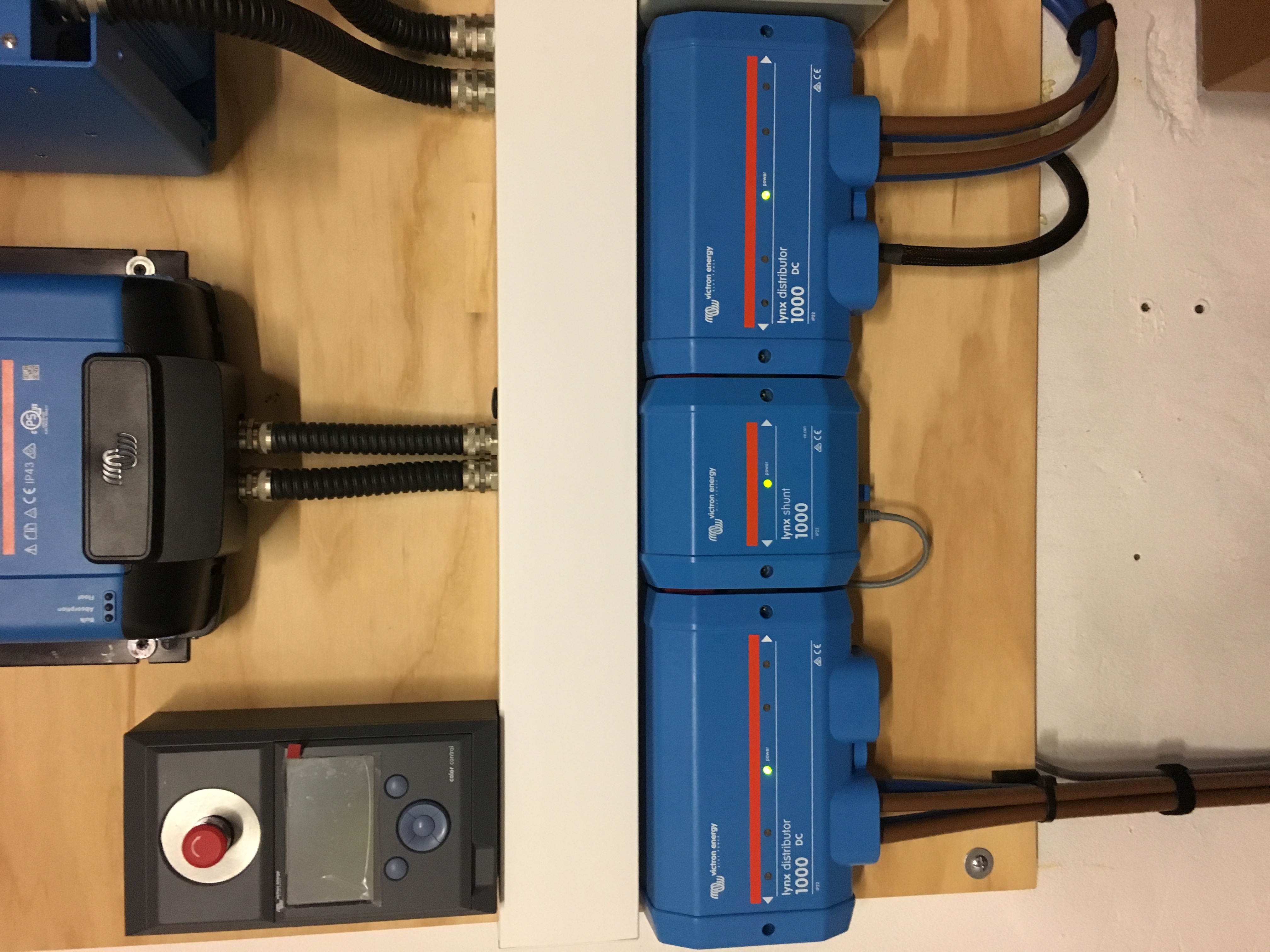
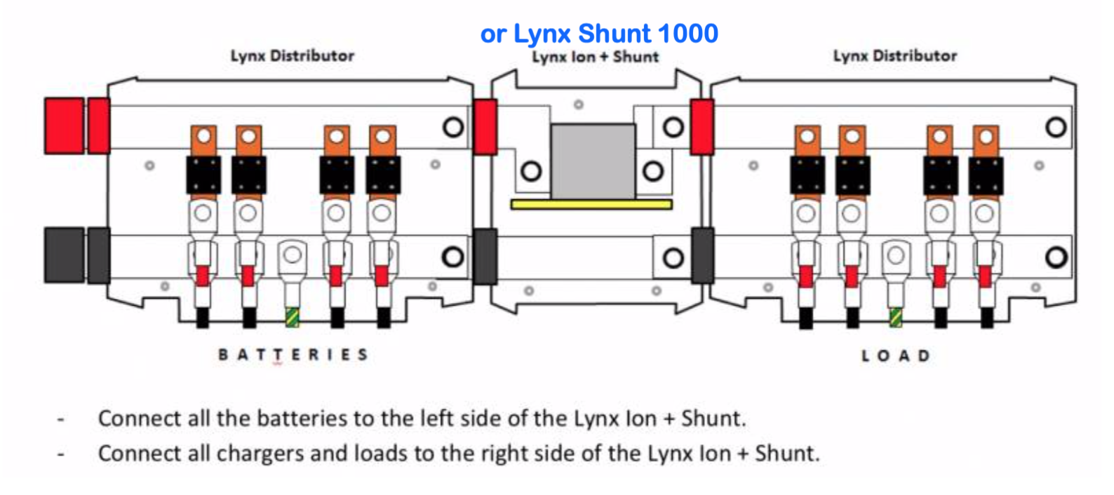
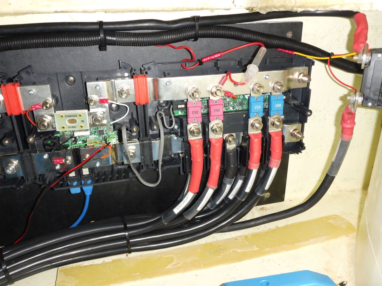
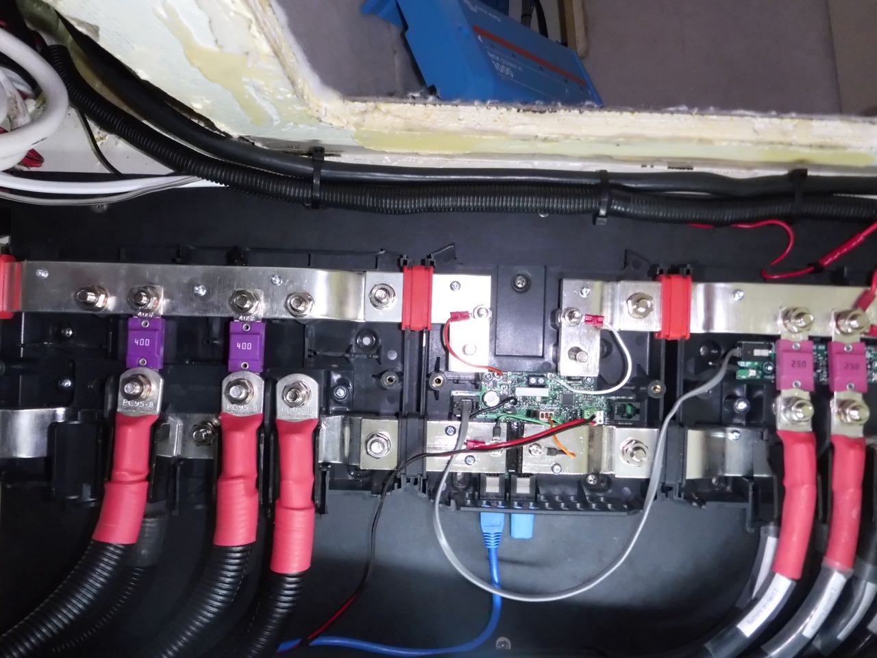
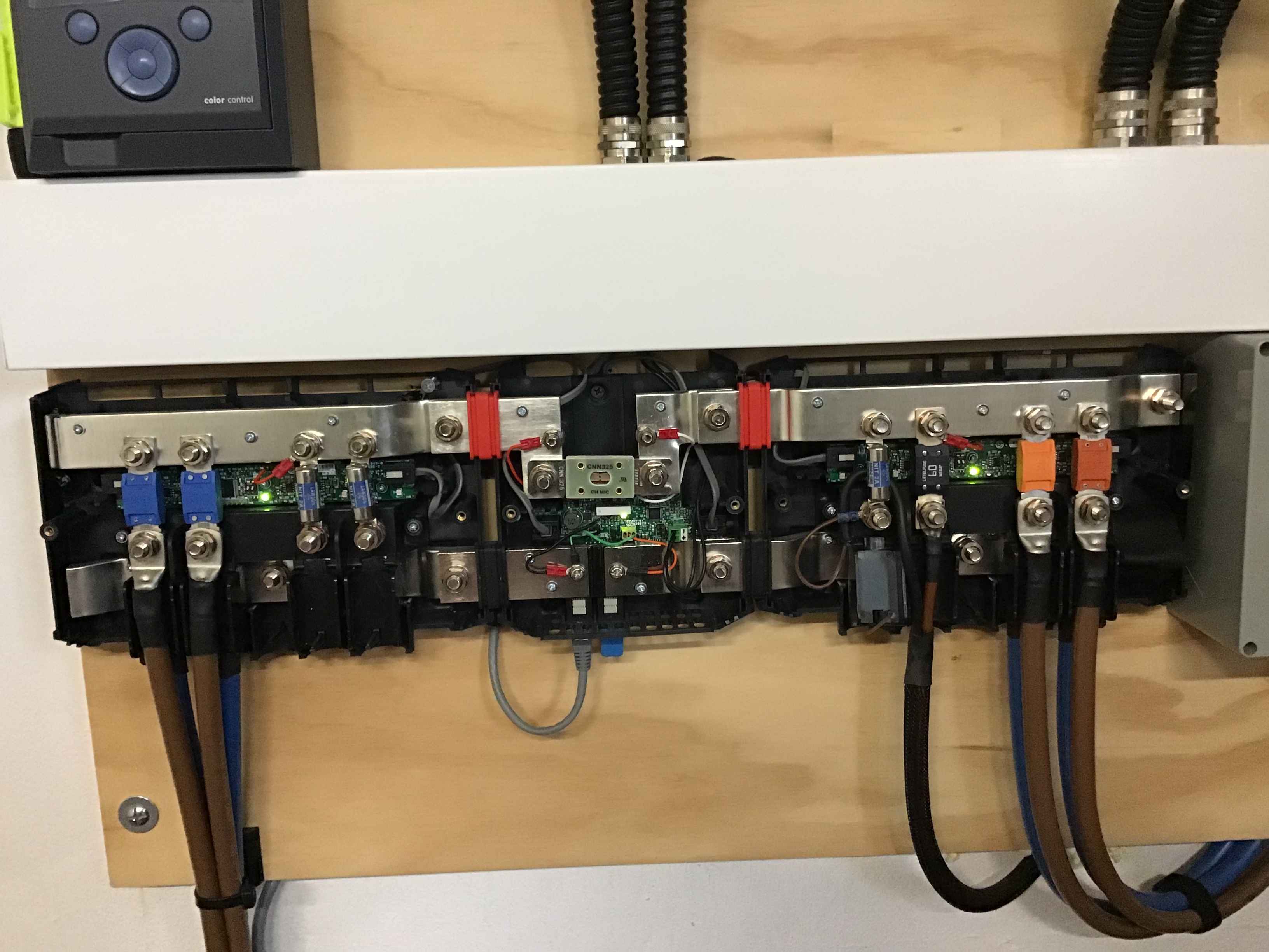
New setup with Lynx Power In, Lynx Shunt 1000 (VE.can) and Lynx Distributor connected to LiPo (24 V 200 AH). All Victron. Downstream are 2 x Battery Protect 220, VE.Bus BMS, Multi 24/5000 and a VenusGX. All 'smart' units have latest firmware.

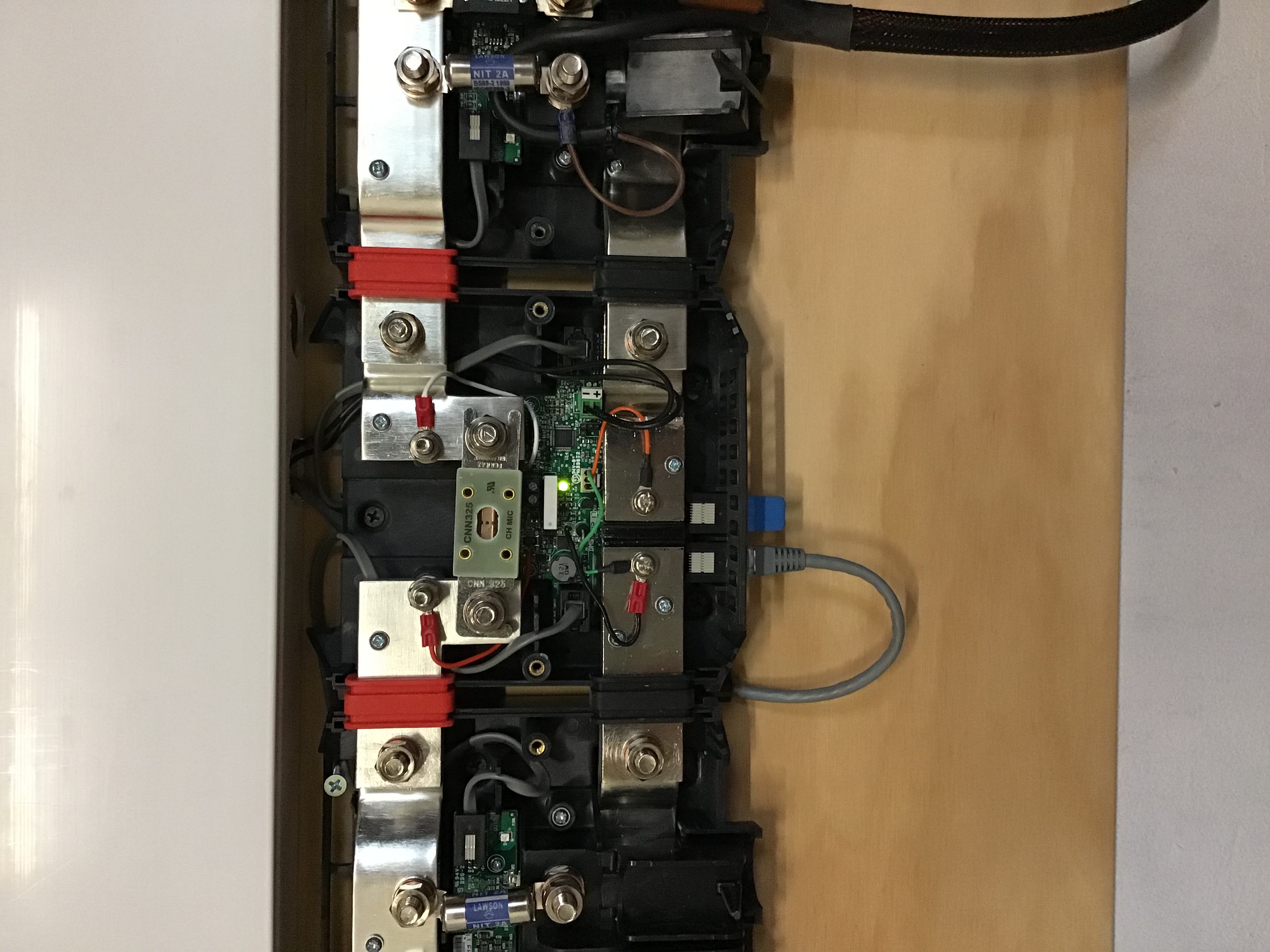
With all loads off there are no lights (LED) on either the Shunt (1) or the Distributor (4)

I have read all of the related posts on this site and in particular the three (3) links that Guy provided to a closely related question.

Have checked all connections to the batteries and both input fuses as well as the shunt fuse. All are OK.

Q1. Any thoughts?

lynx shunt
2 comments
2 |3000

Up to 8 attachments (including images) can be used with a maximum of 190.8 MiB each and 286.6 MiB total.

Michael Riley avatar image Michael Riley commented ·

Additionally - perhaps related to above question (reference extracts below). The small data (R11 presumably) cable supplied with the shunt should go to the Distributor. There are two (2) ports on the Shunt. I have tried both with no success in getting any LEDs illuminated.


Q2. Which of the two ports on the Shunt should be used to power the distributor logic board?

Q3. What is the 'correct' position of this switch? There is no suitable documentation that I can locate which identifies this. Show photo if you can please.


0 Likes 0 ·
Michael Riley avatar image Michael Riley commented ·

Q4. Can any of the 'data' (cat5e) cables be responsible for no LED's?

0 Likes 0 ·
5 Answers
Michael Riley avatar image
Michael Riley answered ·

All, have just now swapped out the Lynx Shunt with a new one. Immediately the 'Light' (Green LED) was on. [Great]. Removed the battery cables [again] and re-connected the Lynx Distributor and reconnected the battery (Power In) fuses. Only three red lights. Nothing on the right hand two LED. Disconnected all and swapped out the Lynx Distributor with a new one. Reconnected the Power In fuses and BINGO - all working. Turned on VE.Direct BMS and Venus and MPPT and MultiPlus.

ALL visible and talking.

Used the local remote logon to VenusGX to check on the new configurations of the Shunt. That is a different topic so will complete that under a new topic heading. Suffice to say that all is now visible on VRM Portal and finally we have a working system. Now just need to complete the test 'program' and then properly commission. After that I can then start swapping over some of my existing 12 VDC loads onto the new 24 V bus and then get out there sailing.....

Once again thanks for the assistance David (Wales UK).


2 |3000

Up to 8 attachments (including images) can be used with a maximum of 190.8 MiB each and 286.6 MiB total.

Mark avatar image
Mark answered ·

I’ve installed a Lynx distributor either side of the shunt using the rj10 cables with no problems, all the Led’s are functional as per the photo!

2 comments
2 |3000

Up to 8 attachments (including images) can be used with a maximum of 190.8 MiB each and 286.6 MiB total.

Mark avatar image Mark commented ·

The green LEDs showing normal operation

0 Likes 0 ·
Michael Riley avatar image Michael Riley Mark commented ·

Thanks Mark for the response,

I ordered 2 x Power In (I even supplied the electrician with the 'Journey with Jono' YouTube on converting Power In) but the local Victron 'expert' sent 1 of each to my electrician as they indicated that this is what was needed (sic).

In any case my installation is not exactly as your one so I have a couple of questions for confirmation if you don't mind.

I presume that this is installed as per the documentation for the Lynx distribution system but for clarity given my experience with the vague (very vague) documentation please confirm:

Q1. that the 'power in' from batteries is on your 'distributor' you have on the left hand side of your photo?

Assuming yes to above the DC loads are on the right. My installation is the same (prior to tidy-up as we are still trying to get this all working) with battery power in to Power In on left - to Shunt - to DC loads (Distributor) on the right.


You will note that I have the RJ11 connected between the Shunts right hand RJ11 socket and the Distributor (only one location). I have tried both Shunt RJ11 locations with no differing result (and no answer to my query on this site and I cannot find if there is a difference or not in the documentation). Why do they need two sockets I wonder?

Your installation appears to have the RJ11 cable going from left hand side 'battery-in' (my Power In) to the Shunt hence the above Q1 clarification question.

Q2. Is your RJ11 connected from Distributor (left = Power In) to the Shunt (centre)?

You mention using "rj11 cables" = plural in your post above.

Q3. Is this exactly correct as I can only see 1 (one) cable in your photo.

Q4. If there is more than one RJ11 cable used is that what the two (2) ports in the Shunt are used for? As I have a Power In there are no LED or circuitry to connect to in any case.

Q5. Can you recall exactly at what step in the assembly/commissioning process that the LED(s) were illuminated?


0 Likes 0 ·
shuntdistributor.jpg (181.2 KiB)
power-inshunt.jpg (144.4 KiB)
Mark avatar image
Mark answered ·

Hi Michael........

A1......the shunt has 2 x rj10 sockets to accommodate 2 distributors either side of the shunt as in my case,to supply power to the onboard pcb present on the distributor.The cable you refer to as on the left in my photo,is a cat5e Ve-Can cable to send the shunt information/programming etc to the CCGX c/w terminator.this required regardless if a Lynx shunt is used or not.

A2....No,your mixing up the rj10 cables with the RJ45.i will post a pic with my covers removed for clarity for you!

A3....as per Answer 2

A4....the 2 rj10 ports are used for coupling up 2 x distributors.only(not used for the power in,hence how you only have 1 rj10 fly lead) the lynx distributors have a pcb to accept the rj10 fly leads,the pcb gives a green led for voltage present,and red leds on each fuse way illuminate if a fuse blows!

A5....as soon as voltage is detected the leds operate! my unused fuse ways have dummy fuses fitted to extinguish the red leds!.also the lynx shunt led flashes until the Ve-Can is properly set up!.

A4....I would say no,because with the cat5e cable disconnected my Lynx system still has all the led functions!


I hope this helps/clarifies feel free to ask any more questions


3 comments
2 |3000

Up to 8 attachments (including images) can be used with a maximum of 190.8 MiB each and 286.6 MiB total.

Mark avatar image Mark commented ·

@Michael Riley pic to follow

0 Likes 0 ·
Mark avatar image Mark commented ·

With covers removed for clarity

0 Likes 0 ·
Mark avatar image Mark commented ·

Lynx shunt

0 Likes 0 ·
Michael Riley avatar image
Michael Riley answered ·

@Mark

Thanks for the details. All as I suspected. Understood your comments. See my new answer below (above this entry apparently)....

1 comment
2 |3000

Up to 8 attachments (including images) can be used with a maximum of 190.8 MiB each and 286.6 MiB total.

Mark avatar image Mark commented ·

Who’s a David? Lol

0 Likes 0 ·
Michael Riley avatar image
Michael Riley answered ·

SUMMARY.

For those who are interested here is what I found out as a result of this problem.

1. Do not discount hardware faults - even on brand new devices. In this case there were two (2) devices. One total failure (Lynx Shunt 1000) and one partial (Lynx Distributor - some LED's not showing).

2. The moment that DC power is applied to the Shunt (in my case 26.x V from LiPo batteries) the Green led lit up. There was no delay or switching. No cables need to be installed (RJ11 or VE.can) - LED on immediately.

3. The Distributor requires power which is supplied through the RJ11 cable connected to the 'working' Lynx Shunt 1000. This RJ11 cable is supplied with the Distributor in the box along with the VE.can terminators. You need to order the Cat5e cable for connecting the VE.can bus to the 'system' seperately. The instance that the Power In fuses were installed the Distributor LED's lit up. There were all red until I turned it all off and then put in the appropriate fuses. When powered up again (note my battery cables are 70mm2 x three off, so no simple task - the Red led had extinguished (fuses are good) and only the single green LED (centre) is on indicating that the Distributor is OK.

4. Connected the other end of the VE.can bus (cat5e) into the VenusGX and logged into the Venus using the local web server. Achieved this by turning on WIFI - connected to the Venus and then swapped application to Safari (yep I am on a MacBook Pro) and entered the IP address (per documentation for local web server), password protected and it immediately showed the new device (Shunt) together with the new MPPT (see below) and the BMS and MultiPlus.

Note that there was a third wiring problem - the Smart Solar (MPPT 150-70Tr) was wired to the Charge disconnect of the VE.Bus BMS using the inverting cable (supplied by the local Victron 'expert' to my electrician. This is wrong. The Smart Solar needs to be connected to the Venus using a VE.Direct to VE.Direct cable (needed to purchase this also today). The Smart Solar MPPT has a VE.Direct port on the left hand bottom side. On the right hand bottom side there is the 'remote' connector which needs to be connected to the BMS Charge Disconnect pin via a simple 'control' wire. Testing this simply involved pulling out the block on the MPPT and the MPPT switched off charging supply within a few seconds.

5. On the Venus all devices can be seen using the local IP address (type in 172.24.24.1 to your 'URL address line of your favourite internet browser) and the Venus local web-server responds) or via the VRM Portal.

6. Connecting a VenusGX to VRM on a sailing boat out at sea was achieved with some difficulty initially. Will use a seperate question/answer to provide details (after this) - title "Venus and VRM on a sailboat".

Hope this helps someone save some time or angst.

@Guy Stewart (Victron Energy Staff)

@Margreet Leeftink (Victron Energy Staff)


1 comment
2 |3000

Up to 8 attachments (including images) can be used with a maximum of 190.8 MiB each and 286.6 MiB total.

cory cantrell avatar image cory cantrell commented ·

I am having similar problems on my install, the Lynx Distributor shows red lights on some of the ports on heavy charging, or heavy load. It isn't always all the ports, just some of them sometimes, or all of them other times, but always red on load or heavy inverter charging. As soon as I remove load the all lights go off (except the center stays green). I have tested every fuse, replaced them, disconnected and reconnected ect. But nothing changes it. I wonder if I also have a lynx distributor hardware fault, as everything else seems to work, just red lights on distributor... 30 hours of hell trying to figure it out and found this which is really similar... This is a new install of 2 new Multiplus-II 120x2 3000 50a in an RV, with 6 lion ut1300 batteries, and 2 250/100 Charge controllers.

0 Likes 0 ·

Related Resources

Lynx Shunt VE Can online manual


Additional resources still need to be added for this topic